
Auto-locking torque distributing mechanism

a technology of torque distribution mechanism and torque distribution, which is applied in mechanical devices, gearing details, gearing, etc., can solve the problems of losing forward momentum, more torque is sent to the wheel that spins uselessly, and all powers are sent to the wheel that spins, so as to maintain the momentum of the vehicle efficiently

Inactive Publication Date: 2015-12-29
LEE KUO MING +1
View PDF12 Cites 0 Cited by
  • Summary
  • Abstract
  • Description
  • Claims
  • Application Information

AI Technical Summary

Benefits of technology

[0006]An objective of the present invention is to provide an auto-locking torque distributing mechanism benefiting to restrict the slipping wheel spinning to a minimum by preventing the slipping wheel from spinning incessantly and distribute the torque to the non-slipping wheel to maintain the traction of the vehicle's momentum efficiently.
[0007]A further object of the present invention is to provide an auto-locking torque distributing mechanism which attains an active flowing design to supplement and circulate the fluid within the mechanism, thereby promoting the speed limitation effect and preventing the slipping wheel from spinning incessantly.
[0008]A further object of the present invention is to provide an auto-locking torque distributing mechanism which simplifies the installation of the configuration and increases the convenience of installation and use.
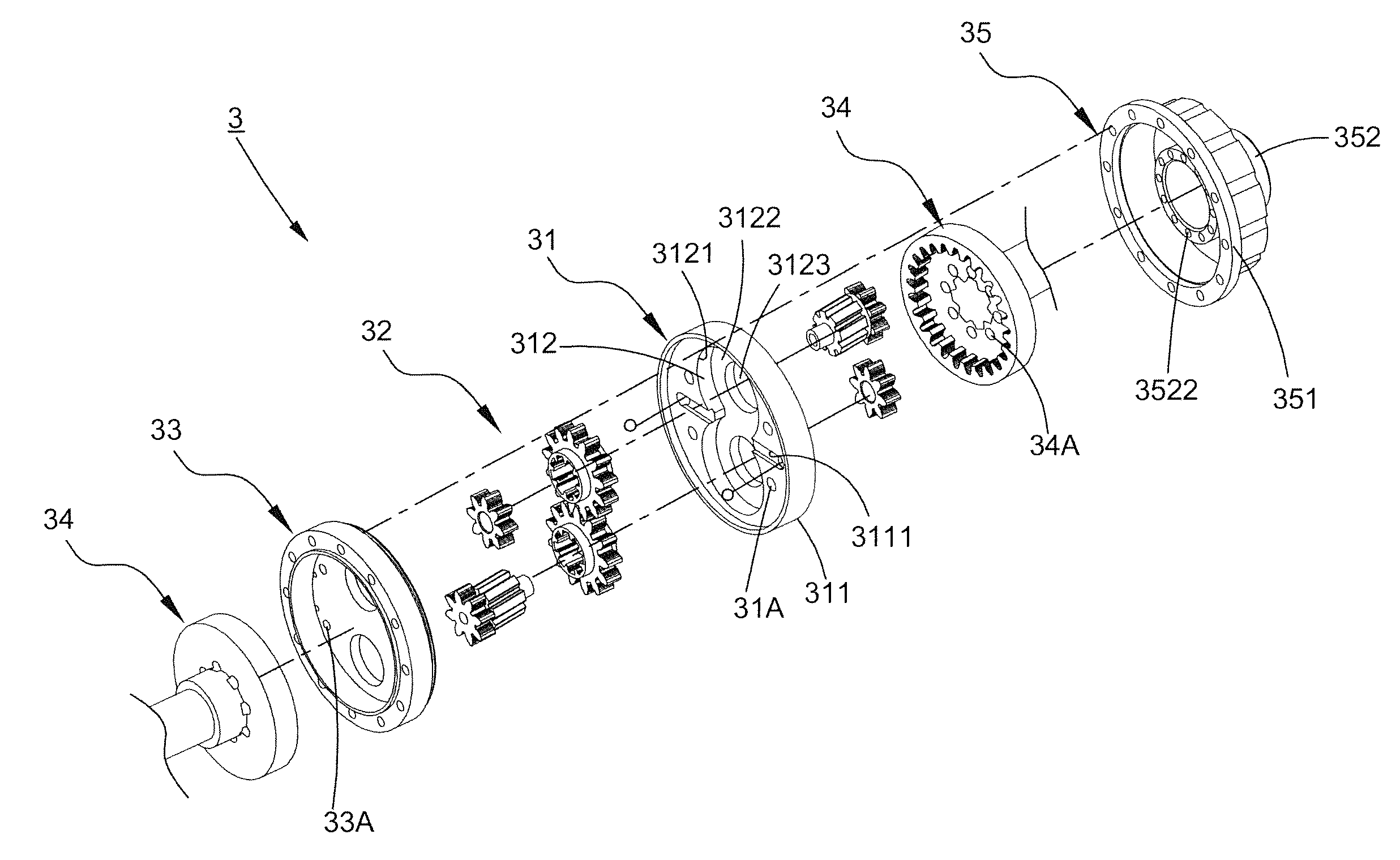
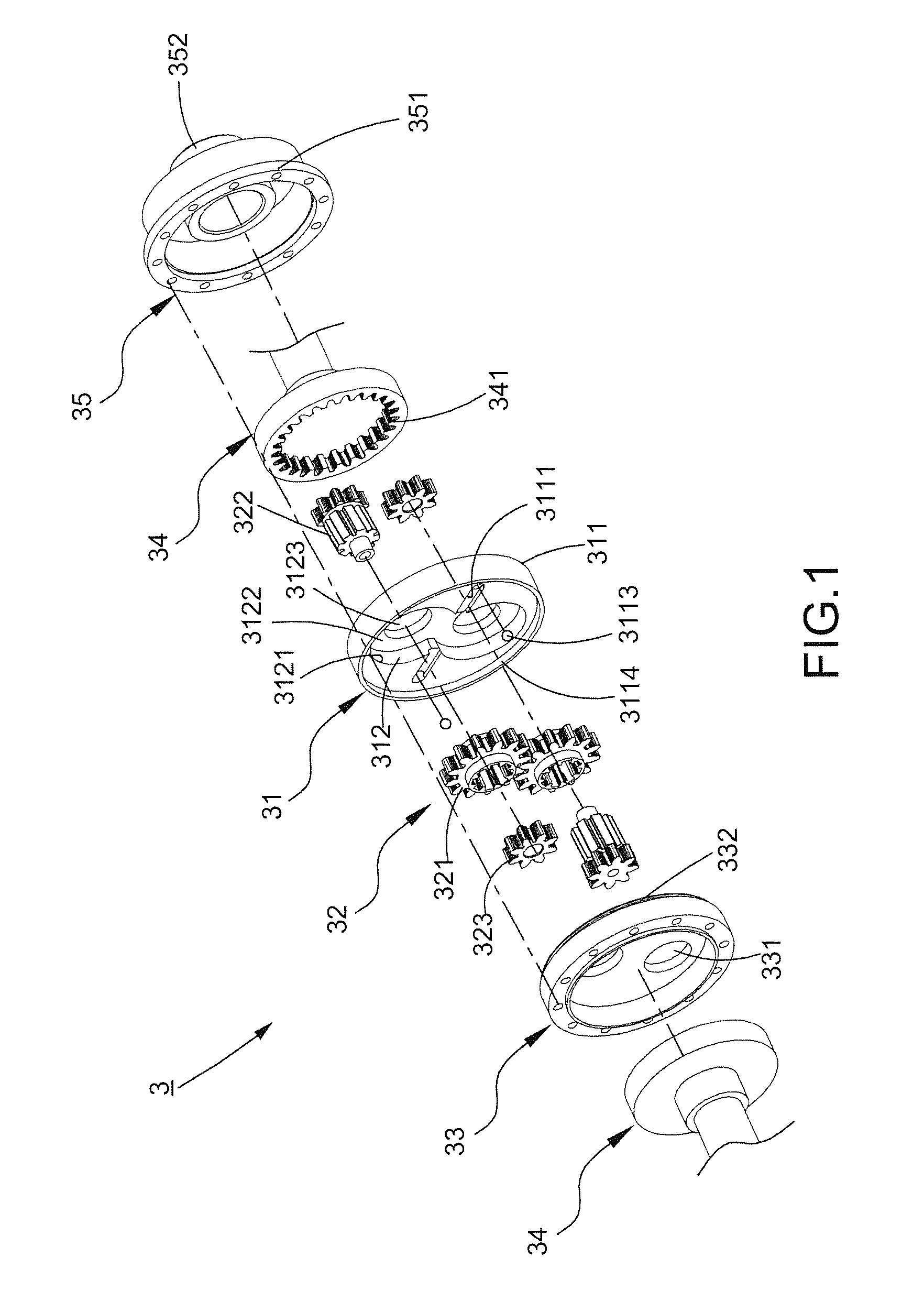
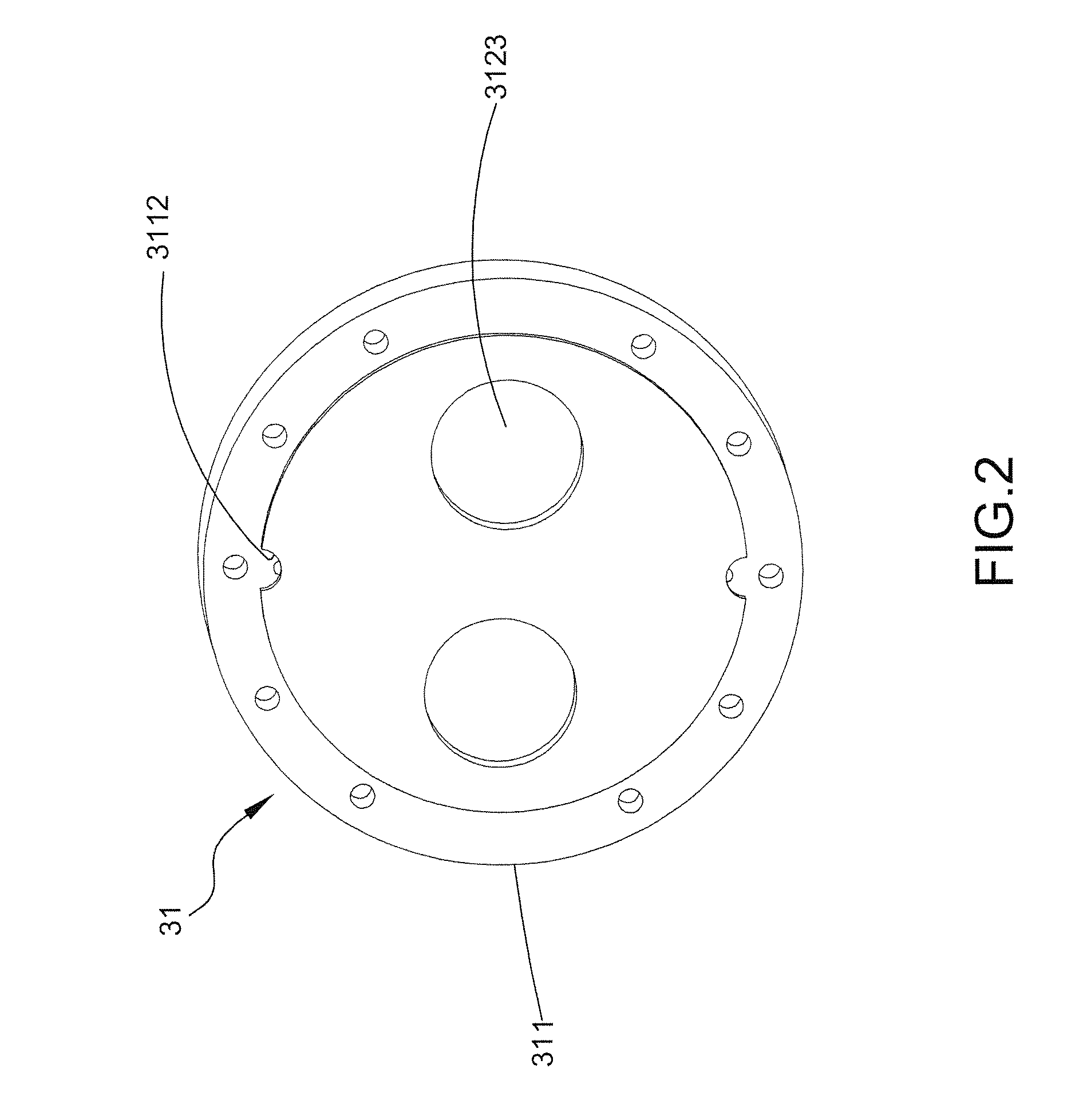
[0009]The auto-locking torque distributing mechanism in accordance with the present invention mainly comprises a main plate, two meshing gear sets disposed on the main plate, a backing plate disposed at one side of the main plate, a transmission assembly connected to two side axles of a vehicle, and a sleeve assembly disposed at the other side of the main plate. The main plate includes a body and a blocking wall recessed into the body, and two sides of the body respectively form slots and apertures which are formed adjacent to the opposite peripheries of the body and partially communicated with each other. The sleeve assembly includes a covering unit and a connecting portion extending outward from the covering unit. A first wall of the covering unit forms an opening, and the connecting portion includes an extension section connected to a second wall of the covering unit and inserted into an interior of the covering unit, whereby each aperture is communicated with the opening and located adjacent to the first wall when the sleeve assembly is connected to the main plate. Accordingly, when one of the wheels slips and spins to exceed a predetermined rotational speed, the cooperation of the main plate and the sleeve assembly keeps fluid in the sleeve assembly efficiently to prevent the leakage. By means of the partial communication between the slots and apertures, the fluid is easily sucked into the apertures to go among the two gear sets via the slots, thereby maintaining sufficient fluid capacity between the gear sets, creating a huge back pressure to limit the slipping wheel spinning to a minimum by preventing it from spinning incessantly and distributing the torque to the non-slipping wheel to maintain the traction of the vehicle.

Problems solved by technology

When one of the wheels on the same axle slips, for instance on icy roads, more torque is sent to the wheel that spins uselessly.
If that slipping wheel completely loses its traction, all powers are sent to that wheel and a forward momentum is inevitably lost.
From a performance standpoint, when a vehicle is cornering or turning and the wheel on the inside of the turn lifts off and begins to slip under the power, a large amount of the power imparted to the slipping wheel causes the wheel to spin more without gripping.
However, in practical, when one wheel slips and spins faster than the other one, the fluid (e.g. engine or machine oil) between the differential gears would be easily drained out of the through-holes, which causes the insufficient fluid capacity in the product and fails to distribute the torque to the two axles evenly.

Method used


Image

  • Auto-locking torque distributing mechanism
  • Auto-locking torque distributing mechanism
  • Auto-locking torque distributing mechanism

Examples


first embodiment

[0035]Referring to FIG. 5 and FIG. 6 shows an auto-locking torque distributing mechanism 3 of the second preferred embodiment comprising the same elements as the first embodiment for the same stated objectives and purposes. In particular, this preferred embodiment includes a plurality of through-holes 3522 formed on the extension section 3521 of the sleeve assembly 35, whereby each aperture 3112 is located with respect to the through-holes 3522 by different horizontal levels (as shown in FIG. 7) when the sleeve assembly 35 is connected to the main plate 31. Further, the body 311 of the main plate 31, each transmission assembly 34, and the backing plate 33 form respective holes 31A, 34A, 33A, thereon, which allow the fluid to circulate within the mechanism 3. Therefore, if part of fluid still leaks to the outside, outer supplemented fluid can be introduced through the through-holes 3522 to allow the fluid to pass the holes 34A directly and enter the interstice between the gear sets 3...

second embodiment

[0036]Referring to FIG. 8 shows an auto-locking torque distributing mechanism 3 of the third preferred embodiment comprising the same elements as the In particular, the main plate 31 and the backing plate 33 further include a first engaging portion 313 and a second engaging portion 333 protruding outward therefrom in different directions, respectively. The first engaging portion 313 and the second engaging portion 333 are hollowly formed to allow the two side axles 4 to insert and position thereto. Further, the main plate 31 forms a first entrance 313A penetrating between a bottom of the first engaging portion 313 and the bottom wall 3122, and the backing plate 33 forms a second entrance 333A penetrating from a bottom of the second engaging portion 333 to the other side of the backing plate 33. The first entrance 313A and the second entrance 333A are located with respect to different horizontal levels and disposed toward the main rooms 3121, whereby these two entrances can face an ...


PUM


Abstract

An auto-locking torque distributing mechanism comprises a main plate receiving two gear sets. On two sides of the main plate, slots and apertures are respectively formed near two side peripheries thereof and partially communicated with each other. A sleeve assembly includes a covering unit with an opening enclosed by a first wall whereby each aperture is communicated with the opening and arranged near the first wall while connecting the main plate to the sleeve assembly. When one wheel slips and spins much faster than the other wheel, the sleeve assembly keeps fluid to avoid leaking. By the aforementioned partial communication, the fluid is easily sucked into the aperture to enter the slot and go among the gear sets, thereby limiting the amount of torque sent to the slipping wheel and distributing as much as torque to the non-slipping wheel to keep the traction of the vehicle.

Description

BACKGROUND OF THE INVENTION[0001]1. Field of the Invention[0002]The present invention relates to a torque distributing structure, particularly to an auto-locking torque distributing mechanism.[0003]2. Description of the Related Art[0004]When one of the wheels on the same axle slips, for instance on icy roads, more torque is sent to the wheel that spins uselessly. If that slipping wheel completely loses its traction, all powers are sent to that wheel and a forward momentum is inevitably lost. From a performance standpoint, when a vehicle is cornering or turning and the wheel on the inside of the turn lifts off and begins to slip under the power, a large amount of the power imparted to the slipping wheel causes the wheel to spin more without gripping. Even though the wheel on the outside of the turn which is on the ground requires more traction, the outside wheel does not receive so many powers since most powers are wasted on the spinning inside wheel. Accordingly, a kind of torque di...

Claims


Application Information

Patent Timeline
Patent Type & Authority Patents(United States)
IPC IPC(8): F16H48/24F16H57/04F16H48/26
CPCF16H48/24F16H48/26F16H57/042F16H57/043F16H57/0421F16H57/0483F16H57/0493F16H57/0495F16H57/0428Y10T74/19074F16H2048/265
Inventor LEE, KUO-MINGHSIEH, YU-AN
Owner LEE KUO MING
Learn More