Garden refuse shredding apparatus

a technology for shredding equipment and garden refuse, which is applied in the direction of solid separation, wet separation, grading, etc., can solve the problems of difficult and unreliable service, dangerous operation around children, and the most suitable for garden mulching

a technology for shredding equipment and garden refuse, which is applied in the direction of solid separation, wet separation, grading, etc., can solve the problems of difficult and unreliable service, dangerous operation around children, and the most suitable for garden mulching

US6910648B1Inactive Publication Date: 2005-06-28BARTLEM

Image

  • Garden refuse shredding apparatus
  • Garden refuse shredding apparatus
  • Garden refuse shredding apparatus

Examples


Embodiment Construction

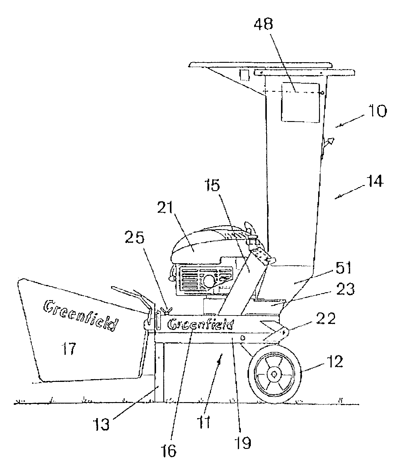
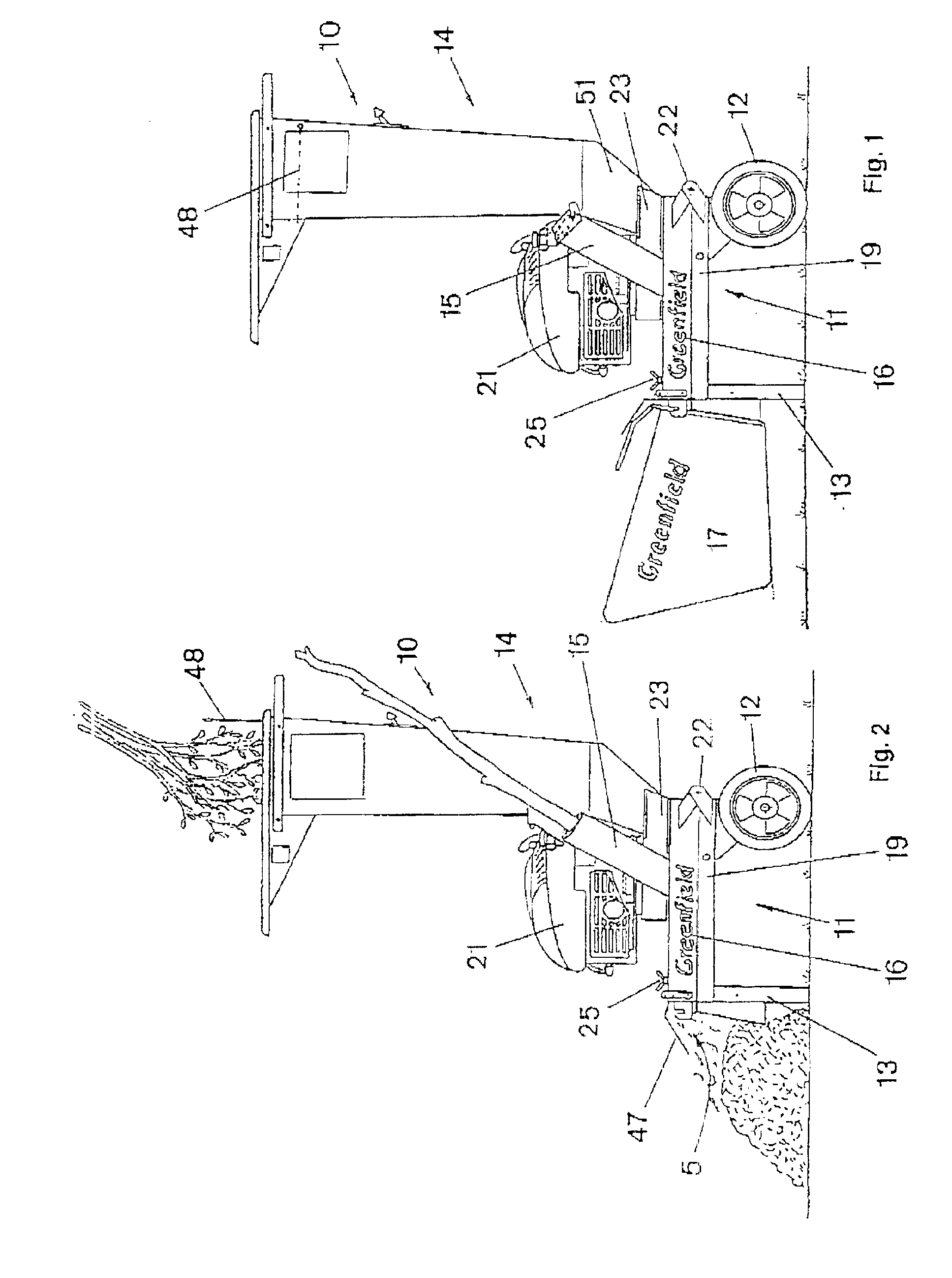
[0067]The garden refuse shredding apparatus 10 illustrated in the drawings has a two-part housing 11 supported on rear wheels 12 and a front stand 13, a feed hopper assembly 14 and a small bore inlet tube 15 extending upwardly from the upper housing part 16 and a catcher 17 suspended from the front of the housing 11.

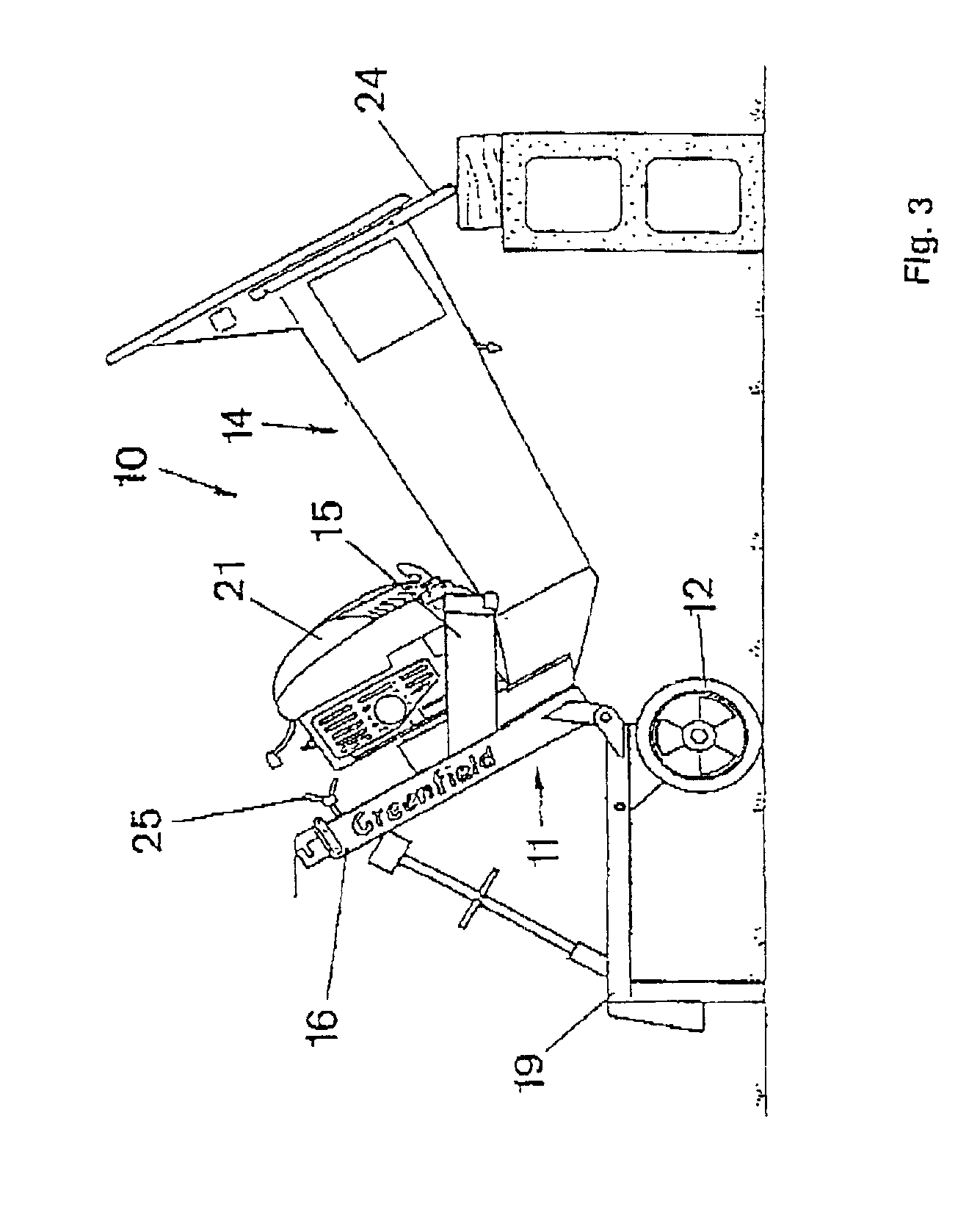
[0068]The housing 11 contains a shredding rotor assembly 20, illustrated in FIG. 4, and supports a small petrol motor 21 thereabove for driving the shredding rotor assembly 20. Opposed pin hinges 22 attach the upper housing part 16 to the lower housing part 19 at the rear thereof which enable the upper housing part 16 and the components mounted thereon to fold to an open position, as illustrated in FIG. 3, at which the handle 24 rests on the ground and clear access is provided to the shredding rotor assembly 20 through the open underside of the top housing part 16. The front of the top housing part 16 is retained on the lower housing part 19, in use, by bolts 25.

[0069]As...


PUM


Abstract

This invention provides garden refuse shredding apparatus (10) which has a chipping rotor (20) supported for rotation about a vertical shaft (31) in a chamber (11) which has a hopper (14) which feeds refuse to radially disposed elongate chipper blades (30) which span a major part of the rotor (28). Fan blades (44) are supported on the rotor for creating an airflow through the hopper (14) to assist feed to the chipping rotor and to assist discharge of shredded refuse from the outlet (45). The chipping rotor (20) is driven directly from the vertical output shaft (36) of an electric motor or a petrol engine (21).

Description

TECHNICAL FIELD[0001]This invention relates to garden refuse shredding apparatus suitable for shredding leaves twigs palm fronds and small branches.BACKGROUND ART[0002]Many types of garden refuse shredders are currently available and typically they include an inlet hopper which can be loaded with garden refuse for shredding as well as a small bore inlet tube for introducing small branches to be shredded. Mostly these machines utilise a flail assembly at the base of the hopper for shredding material fed through the hopper and a separate chipper assembly at the base of the small bore inlet tube for chipping small branches introduced therethrough.[0003]Disadvantages associated with these types of shredders stems from their relative complexity often making servicing, such as drive belt and blade sharpening operations, difficult and unreliable. Furthermore the flail assembly is often readily accessible from the underside of the machine making them dangerous for operation around children....

Claims


Application Information

Patent Timeline
28 Jun 2005
Publication
US6910648B1
IPC
B02C18/08; B02C18/06; B02C18/22; B02C18/18; B02C18/10
CPC
B02C18/083; B02C18/10; A01G3/002; B02C18/2216; B02C18/18; B02C2201/066
Inventors
REINHOLD, THEODORE WILLIAM