
Watch winding device

a technology of a winding device and a watch, which is applied in the direction of electromechanical clocks, regulating apparatuses, repair tools, etc., can solve the problems of inconvenience, small attractiveness of a watch assembled on such a device, and difficult to see objects, etc., and achieve the effect of great security

Inactive Publication Date: 2005-06-28
UNDERWOOD LONDON
View PDF5 Cites 23 Cited by
  • Summary
  • Abstract
  • Description
  • Claims
  • Application Information

AI Technical Summary

Benefits of technology

[0015]The objective of the present invention is to avoid the abovementioned inconveniences, that is, to supply an automatic re-winding device that is compact and modular and that ensures a great security for its use.
[0017]In this way, by means of this presence detector of the watch, the user no longer has to worry about knowing if the re-winding device is on or off; the functioning is ensured from the moment the watch is in place.
[0018]This configuration offers the advantage of eliminating the main switch that could be accidentally activated by movement.
[0024]Another advantage of the configuration according to the invention is that for the first time it can be used in large scale for the shops that offer such watches. In fact, the general cubic shape of these boxes allows the gathering of a great number of them in a reduced space.
[0027]This configuration offers the advantage of not needing the batteries until the re-winding device is separated from the current rail.
[0030]According to another embodiment, the different modules are linked by a control bus that allows to synchronise a set of modules. In this way it is possible to start all the modules at the same time and to set off the cycle changes in a global way.

Problems solved by technology

A first inconvenience of this type of setting is its dimensions that rapidly discourage potential buyers.
Another inconvenience is the little attractiveness of a watch assembled on such a device.
In fact, it is not easy to see the object when it is placed on the base.
Another inconvenience is its continuous functioning, although it is at a low speed.
This implies a permanent current consumption and the need to stop the motor to take the watch from its base.
The consequences can be serious if the re-winding device does not fulfil its mission.

Method used


Image

  • Watch winding device
  • Watch winding device

Examples


Embodiment Construction

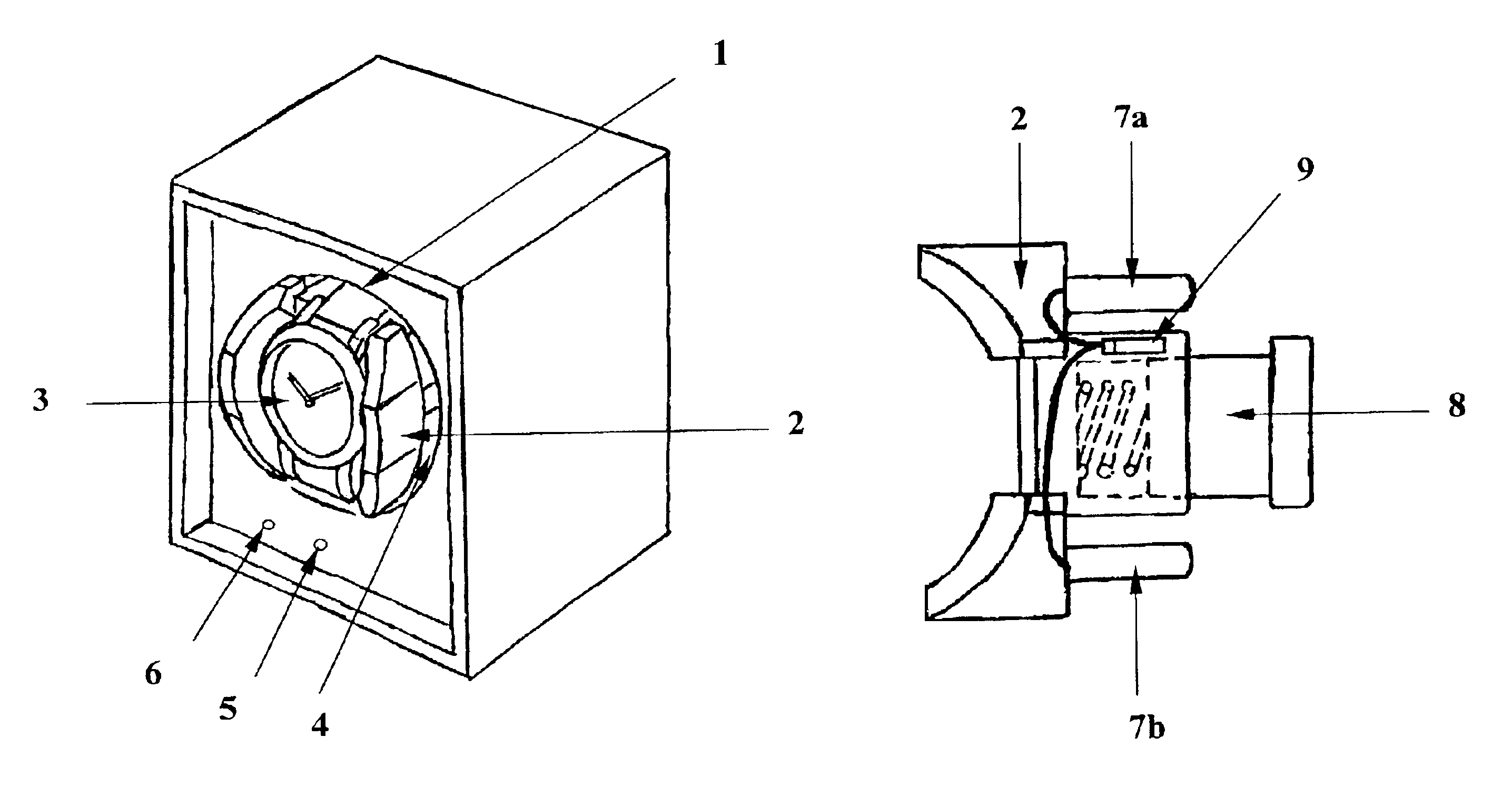
[0035]On the front side of the module is a first green LED 5 to indicate the good functioning of the re-winding device. This luminous indicator is not continuous as the current consumed by the LED is greater than the consumption of the motor, and thus lessens considerably the working life of the batteries. This is why the functioning indication by the green LED 5 is given by means of a slow flashing, for example, one flash every 4 seconds.

[0036]In order to indicate the user that the batteries are running out of power a second red luminous indicator is supplied. In the same way as the functioning indicator, this power indicator of the batteries is intermittent.

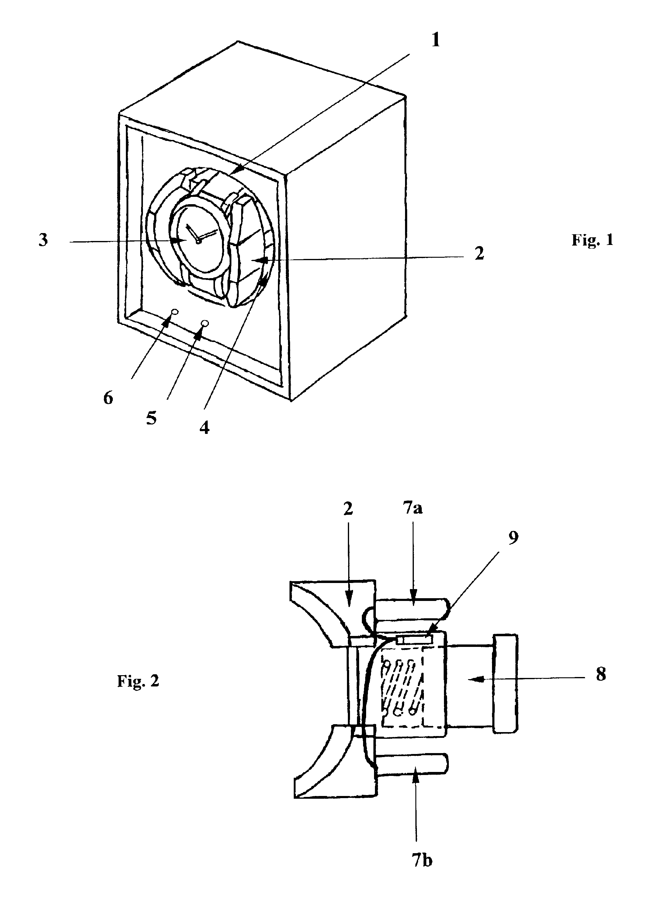
[0037]In FIG. 2 we find the base of the watch 2 when it is separated from the module. In this way, this base is characterised by a simple assembly without lock and using the two axes 7a and 7b which adjust in two orifices of the drum 4 supplied for this purpose. The adjustment between the axes and the orifices is push fit.

[0038...


PUM


Abstract

Automatic watches use the movements of the wrist to re-wind the barrel spring and thus supply the necessary energy for the correct functioning of the watch. When the user cannot wear the watch it is proposed to place it on an automatic re-winding device. The device according to the invention is compact and modular. Furthermore, in order to avoid any error of manipulation, the starting and stopping of the re-winding device is done automatically by means of a detection of the presence of the watch (3). The passing of the strap in the detachable base (2) produces the tension of the device.

Description

BACKGROUND OF THE INVENTION[0001]1. Field of the Invention[0002]The present invention concerns a re-winding device of a watch, particularly for re-winding an automatic watch.[0003]2. Description of Related Art[0004]Such watches work on the principle of movement of the wrist of the user to transmit the necessary energy to the barrel. This movement allows an oscillating mass to drive a set of rotors that, by means of the demultiplication, can supply the energy in order to re-wind the spring of the barrel.[0005]There are mainly two types of oscillating masses for automatic watches, either the complete rotation mass or the limited rotation mass. There are also the masses whose pivoting point is decentred with reference to the axis of the watch.[0006]These differences imply that the movement of an artificial system tending to imitate the movement of the wrist must be compatible with all the automatic watches sold in the shop.[0007]The automatic winding mechanisms are intended to keep an ...

Claims


Application Information

Patent Timeline
IPC IPC(8): G04D7/00
CPCG04D7/009
Inventor RUSTIONI, ALESSANDRO
Owner UNDERWOOD LONDON
Learn More