Single-hand operable microdermabrasion device

a microdermabrasion device and single-hand technology, applied in the field of microdermabrasion devices, can solve the problems of undesirable residue that must be properly disposed of, high cost of treatment, and additional precautions,

Inactive Publication Date: 2005-06-28
IVORY COURT LLC +1
View PDF29 Cites 59 Cited by
  • Summary
  • Abstract
  • Description
  • Claims
  • Application Information

AI Technical Summary

Problems solved by technology

However, such treatments are often expensive, require additional precautions, and often leave undesirable residue that must be properly disposed after treatment.
Such additional treatments also limit the ability to treat the patient to an office setting or other controlled environment.

Method used


Image

  • Single-hand operable microdermabrasion device
  • Single-hand operable microdermabrasion device
  • Single-hand operable microdermabrasion device

Examples


Embodiment Construction

[0012]Persons of ordinary skill in the art will realize that the following description is illustrative only and not in any way limiting. Other modifications and improvements will readily suggest themselves to such skilled persons having the benefit of this disclosure. In the following description, like reference numerals refer to like elements throughout.

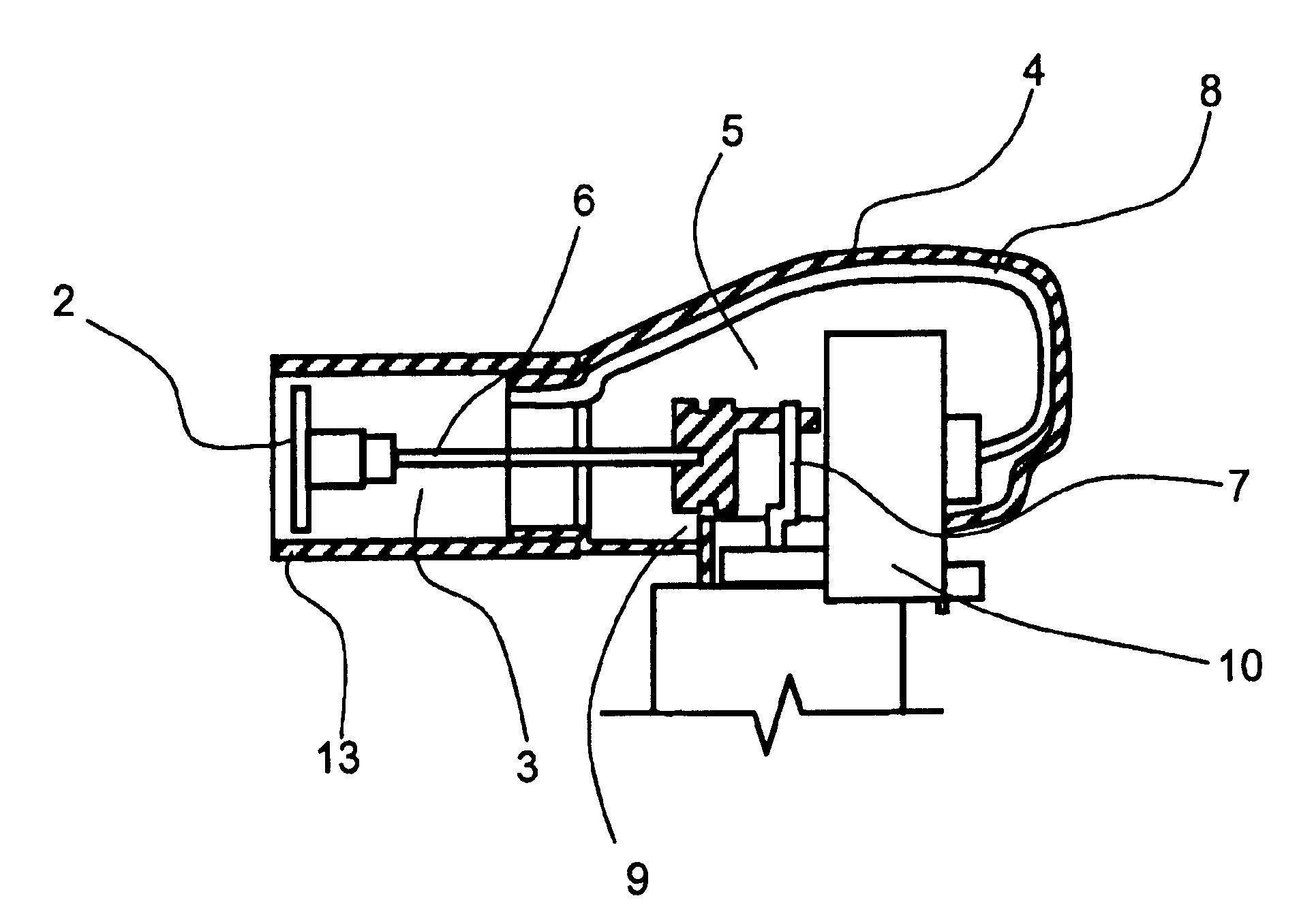
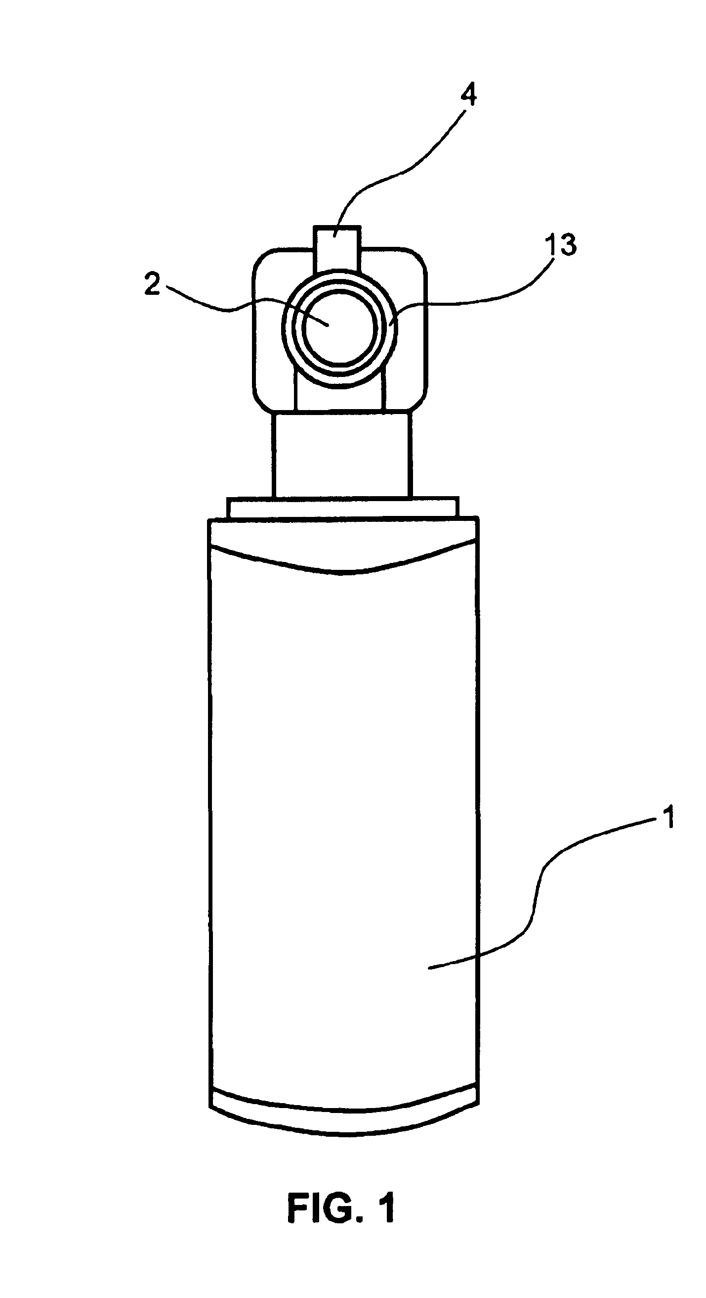
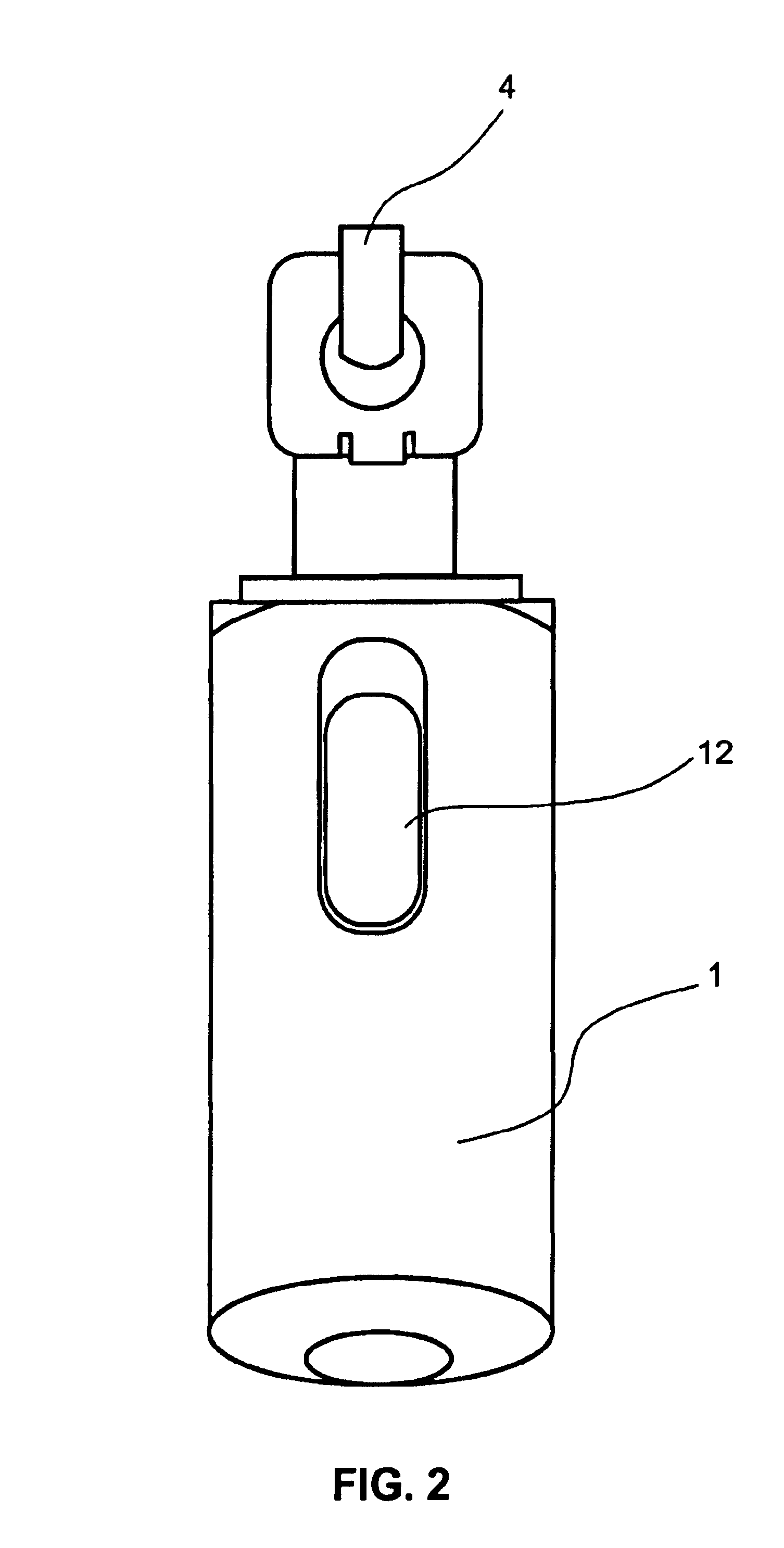
[0013]FIG. 1 is a front view of a microdermabrasion device configured in accordance with the teachings of this disclosure. The device includes a body 1 that is coupled to a partial vacuum housing 4 through motor housing 10 having a motor. The body 1 may be formed of materials known in the art, such as injection molded plastics and the like. The body may contain a conventional power source (not shown), such as a battery, for powering the device.

[0014]FIG. 1 also shows a front view of the outer abrading surface of a disposable abrading attachment 2 disposed within a removable housing 13, in a manner more fully disclosed below. In pref...


PUM


Abstract

A microdermabrasion device is disclosed for removing cells from a patient's skin. The device includes a partial vacuum channel for drawing skin into intimate contact with an abrasive surface and drawing away removed skin cells.

Description

BACKGROUND[0001]1. Field of the Disclosure[0002]The disclosure relates generally to microdermabrasion devices for removing dead dry surface portions of tissue.[0003]2. The Prior ArtBACKGROUND[0004]Microdermabrasion is a process for removing undesirable outer layers of the skin, resulting in a cleaner skin and enhanced skin tone. Problem areas of the skin, such as acne scars, age spots, and sun damaged skin may be removed to improve the patient's appearance.[0005]One current trend is to utilize additional surface treatments to enhance the abrasion process, such as chemicals or additional abrasives. However, such treatments are often expensive, require additional precautions, and often leave undesirable residue that must be properly disposed after treatment. Such additional treatments also limit the ability to treat the patient to an office setting or other controlled environment.BRIEF DESCRIPTION OF THE DRAWING FIGURES[0006]FIG. 1 is a front view of a microdermabrasion device configu...

Claims


Application Information

Patent Timeline
Patent Type & Authority Patents(United States)
IPC IPC(8): A61B17/54A61B17/32
CPCA61B17/54A61B2017/320004
Inventor MULDNER, JANELLE MARIE
Owner IVORY COURT LLC
Why Eureka
Try Eureka