Systems and methods for electrosurgical removal of the stratum corneum

a stratum corneum and electrosurgical technology, applied in the field of electrosurgical removal, can solve the problems of collateral tissue damage, patient discomfort, dermabrasion and chemical procedures, etc., and achieve the effects of reducing the temperature of the conductive fluid, avoiding or minimizing current shorting, and minimizing the amount of conductive fluid

Inactive Publication Date: 2010-07-20
ARTHROCARE
View PDF482 Cites 39 Cited by
  • Summary
  • Abstract
  • Description
  • Claims
  • Application Information

AI Technical Summary

Benefits of technology

[0012]In one aspect of the invention, a method includes positioning an active electrode adjacent to or near a target site on a patient's outer skin, and applying a sufficient high frequency voltage to the active electrode to remove the stratum corneum without removing the entire epidermis layer. In this manner, the present invention removes dead and / or damaged skin cells on the surface of the skin which improves the overall appearance of the skin. In addition, this process helps to stimulate the bodies own rejuvenation process. In some embodiments, this rejuvenation process occurs by the actual removal of the stratum corneum, which accelerates the regrowth of new cell layers in the skin. In other embodiments, thermal energy is applied to the underlying epidermis and / or dermis to stimulate the growth of new collagen. In both of these embodiments, the skin appears healthier and, in some cases, small wrinkles are removed or reduced.
[0014]In another aspect of the invention, a layer of skin is ablated at relatively low temperatures to minimize collateral damage, and, in some cases, to allow the procedure to be performed without administering anesthesia to the patient. In one embodiment, an active electrode is positioned adjacent to or near the target site on a patient's skin, and sufficient high frequency voltage is applied to the active electrode to ablate an outer layer of tissue at the target site while maintaining a temperature of the exposed surface of the underlying layer less than about 50° C., preferably less than about 40° C.
[0015]In the exemplary embodiments, the stratum corneum tissue is ablated with molecular dissociation or disintegration processes. Conventional electrosurgery cuts through tissue by rapidly heating the tissue until cellular fluids explode, producing a cutting effect along the pathway of localized heating. The present invention volumetrically removes the tissue in a cool ablation process that minimizes thermal damage to surrounding tissue. In these processes, the high frequency voltage applied to the active electrode(s) is sufficient to vaporize the electrically conductive fluid (e.g., gel or saline) between the electrode(s) and the tissue. Within the vaporized fluid, a ionized plasma is formed and charged particles (e.g., electrons) are accelerated towards the tissue to cause the molecular breakdown or disintegration of several cell layers of the tissue. This molecular dissociation is accompanied by the volumetric removal of the tissue. The short range of the accelerated charged particles within the plasma layer confines the molecular dissociation process to the surface layer to minimize damage and necrosis to the underlying tissue. This process can be precisely controlled to effect the volumetric removal of tissue as thin as 10 to 50 microns with minimal heating of, or damage to, surrounding or underlying tissue structures. A more complete description of this phenomena is described in commonly assigned U.S. Pat. No. 5,697,882, the complete disclosure of which is incorporated herein by reference.
[0018]In another embodiment, the method further includes the step of vaporizing the electrically conductive fluid near the active electrode into a plasma at relatively low temperatures, preferably lower than about 100° C., more preferably lower than about 80° C. The lower temperature of the conductive fluid will further reduce any risk of undesired thermal damage to tissue surrounding the target site and provide an even more precise tissue removal. In one aspect of the invention, the electrically conductive fluid itself has a relative low vaporization temperature (e.g., preferably below about 100° C. or below 80° C.) at atmospheric pressure. In other embodiments, the electrically conductive fluid is cooled to temperatures less than about 30° C., usually less than 10° C., prior to delivery of this fluid to the target site.
[0020]In a specific configuration, the apparatus includes a supply of electrically conductive fluid and a fluid delivery element for delivering electrically conducting fluid to the electrode terminal(s) and the target site. The fluid delivery element may be located on the instrument, e.g., a fluid lumen or tube, or it may be part of a separate instrument. Alternatively, an electrically conducting gel or spray, such as a saline electrolyte or other conductive gel, may be applied to the target site. In this embodiment, the apparatus may not have a fluid delivery element. In both embodiments, the electrically conducting fluid will preferably generate a current flow path between the active electrode(s) and one or more return electrode(s). In an exemplary embodiment, the return electrode is located on the instrument and spaced a sufficient distance from the active electrode(s) to substantially avoid or minimize current shorting therebetween and to shield the return electrode from tissue at the target site.
[0021]The electrosurgical instrument will preferably include an electrically insulating electrode support member, preferably an inorganic support material (e.g., ceramic, glass, glass / ceramic, etc.) having a tissue treatment surface at the distal end of the instrument shaft. One or more electrode terminal(s) are coupled to, or integral with, the electrode support member such that the electrode terminal(s) are spaced from the return electrode. In a specific configuration, the electrosurgical instrument includes an insulating member around the active electrode(s) that forms a plasma chamber adjacent to the active electrode(s). The insulating member preferably comprises an inorganic material, such as ceramic or glass, and it may comprise a transparent material that allows the physician to view the plasma formed therein. In some embodiments, the return electrode(s) are positioned exterior to the plasma chamber, proximally spaced on the instrument as described above. In other embodiments, the return electrode(s) may be positioned within the insulating member such that the electric currents are completely confined to the plasma chamber. In one configuration, the instrument further include a fluid lumen for delivering electrically conductive fluid to the plasma chamber, and a second fluid lumen for aspirating excess conductive fluid from the plasma chamber. The fluid lumens create a fluid recirculation system for minimizing the amount of conductive fluid that leaks onto the patient and for reducing the temperature of the conductive fluid in and around the plasma chamber.

Problems solved by technology

These dermabrasion and chemical procedures, however, are difficult to control, requiring great surgical skill.
In addition, these somewhat inelegant techniques often cause excessive bleeding, collateral tissue damage and patient discomfort.
Although initially encouraging, lasers suffer from a number of drawbacks in dermatology procedures.
In the first place, laser equipment can be very expensive because of the costs associated with the laser light sources.
Moreover, those lasers which permit acceptable depths of necrosis (such as excimer lasers, erbium:YAG lasers, and the like) provide a very low volumetric ablation rate, requiring numerous passes over the same treatment area which amounts to longer procedural times. In addition, erbium:YAG lasers generally do not provide effective hemostasis during the procedure, resulting in excessive bleeding which disrupts the surgeon's view of the treatment site.
On the other hand, CO2 lasers often create significant residual thermal injury to tissue at and surrounding the treatment site, which requires long healing periods for the patient.
In addition, CO2 lasers are associated with much pain and, therefore, require a lot of anesthesia, which increases the cost and length of the procedure.
These electrosurgical devices and procedures, however, suffer from a number of disadvantages.
At the point of contact of the electric arcs with tissue, rapid tissue heating occurs due to high current density between the electrode and tissue.
This cutting effect generally results in the production of smoke, or an electrosurgical plume, which can spread bacterial or viral particles from the tissue to the surgical team or to other portions of the patient's body.
In addition, the tissue is parted along the pathway of evaporated cellular fluid, inducing undesirable collateral tissue damage in regions surrounding the target tissue site.
For one thing, the crystal grains are difficult to remove once they are embedded into the skin, which has generated some health concerns.
In addition, these crystals may often get into the patient's airways or eyes, causing sneezing or other discomfort during the procedure.
Moreover, the crystals may scratch the skin or cause minor scarring or discoloration on the neck or darker skins.
Finally, since this procedure does not involve the application of heat, it may not have any effect on the underlying collagen in the epidermis and the dermis.
Thus, it may not reduce the underlying wrinkles or stimulate any new collagen growth, as claimed in the early marketing studies of this process.

Method used


Image

  • Systems and methods for electrosurgical removal of the stratum corneum
  • Systems and methods for electrosurgical removal of the stratum corneum
  • Systems and methods for electrosurgical removal of the stratum corneum

Examples


Embodiment Construction

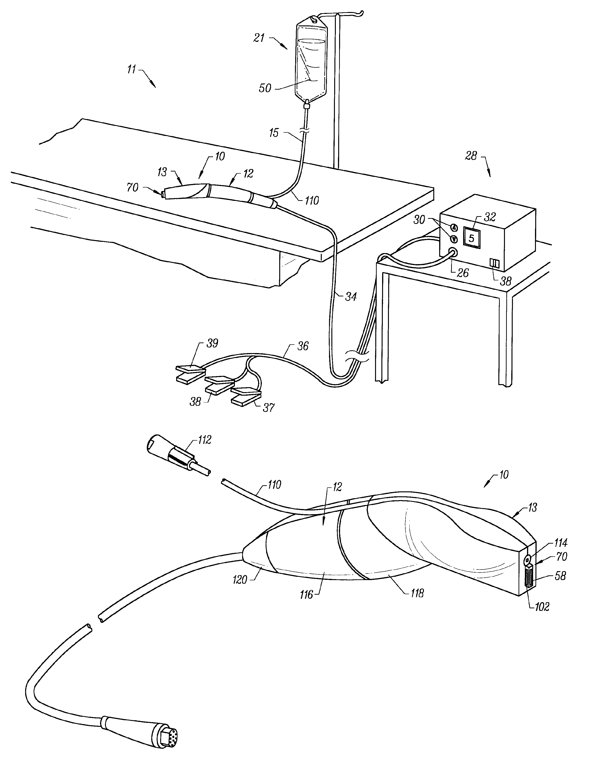
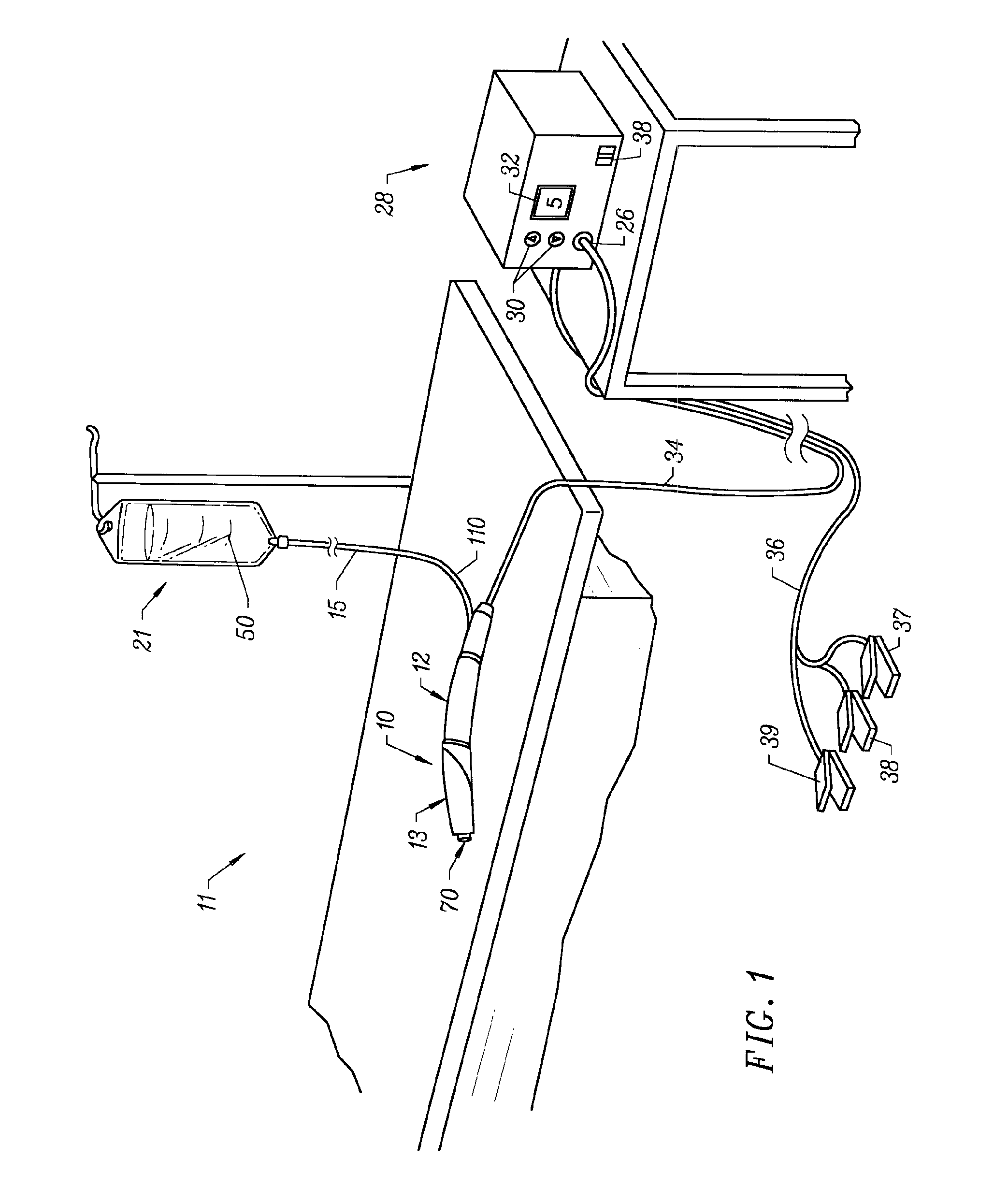
[0040]The present invention provides systems and methods for selectively applying electrical energy to a target location within or on a patient's body, particularly including procedures on an external body surface, such as collagenous tissue within the eye and epidermal and dermal tissues in the skin. For convenience, the remaining disclosure will be directed specifically to skin tissue removal and / or the stimulation of collagen growth in the epidermis or dermis, e.g., the removal of the stratum corneum layer. However, it will be appreciated that the system and method can be applied equally well to procedures involving other tissues of the body, as well as to other procedures including open procedures, intravascular procedures, interventional cardiology procedures, urology, laparascopy, arthroscopy, thoracoscopy or other cardiac procedures, cosmetic surgery, orthopedics, gynecology, otorhinolaryngology, spinal and neurologic procedures, oncology and the like.

[0041]The present invent...


PUM


Abstract

The present invention provides systems, apparatus and methods for removing the outer layer, or stratum corneum, of a patient's skin. In one aspect of the invention, a method includes positioning an active electrode adjacent to or near a target site on a patient's outer skin, and applying a sufficient high frequency voltage to the active electrode to remove the stratum corneum without removing the entire epidermis layer. In this manner, the present invention removes dead and / or damaged skin cells on the surface of the skin which improves the overall appearance of the skin. In addition, this process helps to stimulate the bodies own rejuvenation process. In some embodiments, this rejuvenation process occurs by the actual removal of the stratum corneum, which accelerates the regrowth of new cell layers in the skin. In other embodiments, thermal energy is applied to the underlying epidermis and / or dermis to stimulate the growth of new collagen. In both of these embodiments, the skin appears healthier and, in some cases, small wrinkles are removed or reduced.

Description

RELATED APPLICATIONS[0001]The present invention is a continuation-in-part of U.S. patent application Ser. Nos. 08 / 977,845, now U.S. Pat. No. 6,210,402, and 09 / 248,763, now U.S. Pat. No. 6,149,620, filed Nov. 25, 1997, and Feb. 12, 1999, respectively. U.S. patent application Ser. No. 08 / 977,845 is a continuation-in-part of U.S. patent application Ser. No. 08 / 562,332, filed Nov. 22, 1995, now U.S. Pat. No. 6,024,733, the complete disclosures of which are incorporated herein by reference for all purposes.[0002]The present invention is also related to commonly assigned U.S. patent application Ser. No. 08 / 990,374, filed Dec. 15, 1997, now U.S. Pat. No. 6,109,268, which is a continuation in part of U.S. patent application Ser. No. 08 / 485,219, filed on Jun. 7, 1995, now U.S. Patent No. 5,697,281, patent application Ser. Nos. 09 / 109,219, now abandoned, 09 / 058,571, now U.S. Pat. No. 6,142,992, 08 / 874,173, now U.S. Pat. No. 6,179,824, and 09 / 002,315, now U.S. Pat. No. 6,183,469, filed on Jun....

Claims


Application Information

Patent Timeline
Patent Type & Authority Patents(United States)
IPC IPC(8): A61B17/20A61B17/00A61B18/12A61B18/14A61N1/06
CPCA61N1/06A61B18/1402A61B2017/00761
Inventor BRUNELL, STEPHEN M.WOLOSZKO, JEANBAKER, MICHAEL A.THAPLIYAL, HIRA V.EGGERS, PHILIP E.
Owner ARTHROCARE
Why Eureka
Try Eureka