Current controlled delay circuit

a delay circuit and current control technology, applied in pulse generators, pulse manipulation, pulse techniques, etc., can solve the problems of more difficult stability design of plls, increased output noise of plls, delay modulation,

Inactive Publication Date: 2005-06-28
CYPRESS SEMICON CORP
View PDF5 Cites 75 Cited by
  • Summary
  • Abstract
  • Description
  • Claims
  • Application Information

AI Technical Summary

Problems solved by technology

Rapid changes in VC and R can cause short-term amplitude modulation in VOUT-MAX, which will cause delay modulation.
PLL stab

Method used


Image

  • Current controlled delay circuit
  • Current controlled delay circuit
  • Current controlled delay circuit

Examples


Embodiment Construction

[0016]Embodiments of a current controlled delay circuit are described. In the following description, numerous specific details are set forth. However, it is understood that embodiments of the invention may be practiced without these specific details. In other instances, well-known circuits, structures and techniques have not been shown in detail in order not to obscure the understanding of this description.

[0017]Reference throughout this specification to “one embodiment” or “an embodiment” means that a particular feature, structure, or characteristic described in connection with the embodiment is included in at least one embodiment of the invention. Thus, the appearances of the phrases “in one embodiment” or “in an embodiment” in various places throughout this specification are not necessarily all referring to the same embodiment. Furthermore, the particular features, structures, or characteristics may be combined in any suitable manner in one or more embodiments.

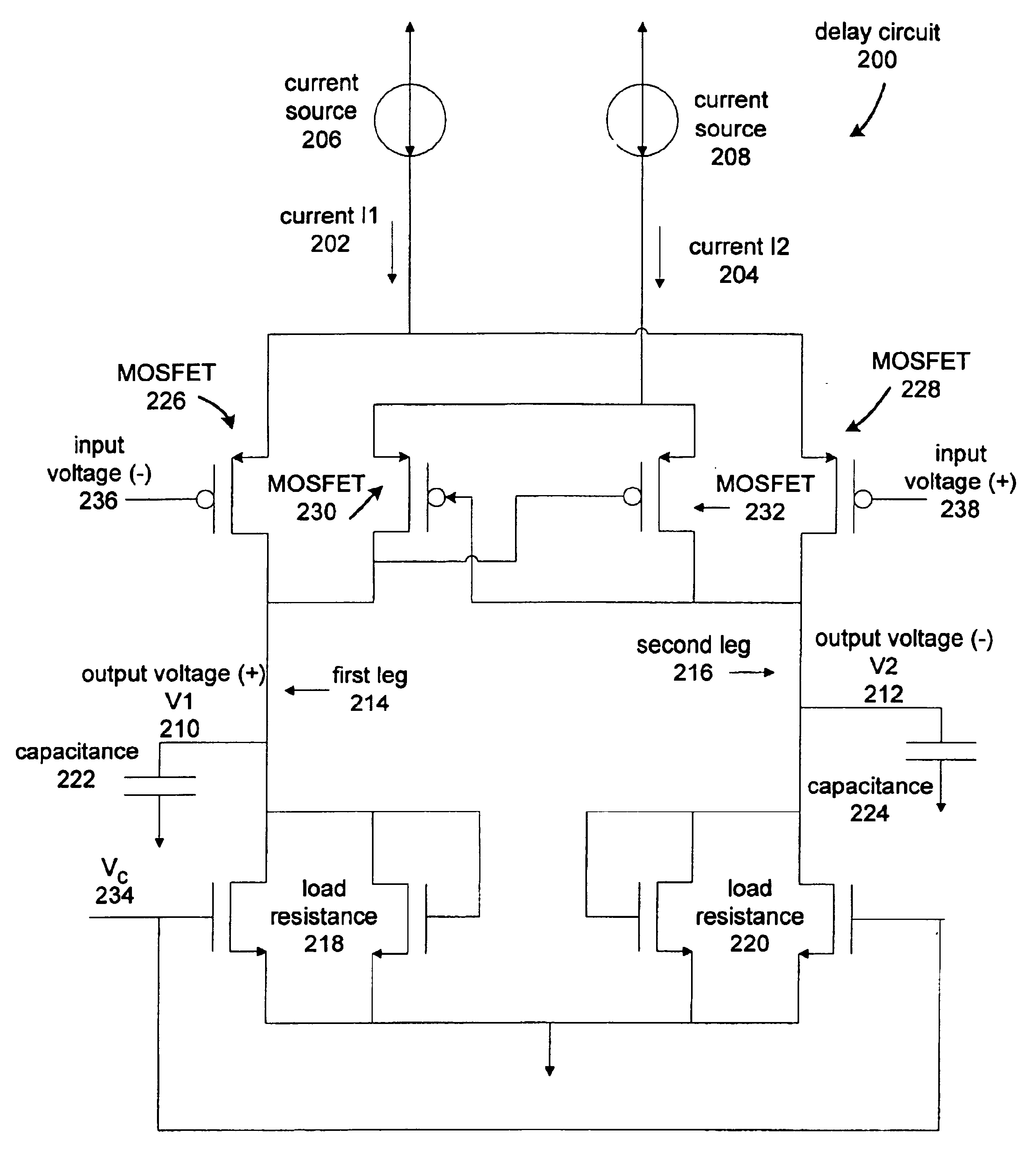
[0018]Referring to ...


PUM


Abstract

A current controlled delay circuit is disclosed. Two currents of constant sum are generated to control the delay of the circuit. The circuit includes a differential pair to switch one of the two currents from one leg of the circuit to another leg of the circuit. The circuit includes a cross-coupled pair to switch the other of the two currents from one leg of the circuit to another leg of the circuit. The circuit may include a fixed or variable load.

Description

TECHNICAL FIELD[0001]Embodiments of the invention generally relate to the field of delay circuitry, and more specifically, to a current controlled delay circuit.BACKGROUND[0002]A conventional delay cell 100 is shown in FIG. 1. The delay cell 100 includes a plurality of Metal-Oxide Semiconductor Field-Effect Transistors (MOSFETs), such as 104 and 106. MOSFETs 104 and 106 comprise a differential pair, which switches the current 110 from one output leg to another output leg based on the voltage difference between input voltages 112 and 114. When the difference between input voltages 112 and 114 is greater than zero, current 110 flows in output leg 120. If the difference between the input voltages is less than zero, current flows in output leg 122.[0003]The delay cell 100 includes a current source 108, voltage-controlled resistances 124 and 126, and output load capacitances 130 and 132. The voltage-controlled resistances 124 and 126 control the delay of the circuit 100. The delay is def...

Claims


Application Information

Patent Timeline
IPC IPC(8): H03K5/13H03K17/28H03K3/356H03K5/00H03K17/041
CPCH03K3/356139H03K5/133H03K17/04106H03K2005/00208H03K2005/00026
Inventor STIFF, JONATHON C.
Owner CYPRESS SEMICON CORP
Why Eureka
Try Eureka