Eureka AIR delivers breakthrough ideas for toughest innovation challenges, trusted by R&D personnel around the world.

Dynamic logic algorithm used for detecting slow-moving or concealed targets in synthetic aperture radar (SAR) images

Inactive Publication Date: 2005-06-28
AIR FORCE GOVERNMENT OF THE US SEC THE
View PDF5 Cites 44 Cited by
  • Summary
  • Abstract
  • Description
  • Claims
  • Application Information

AI Technical Summary

Benefits of technology

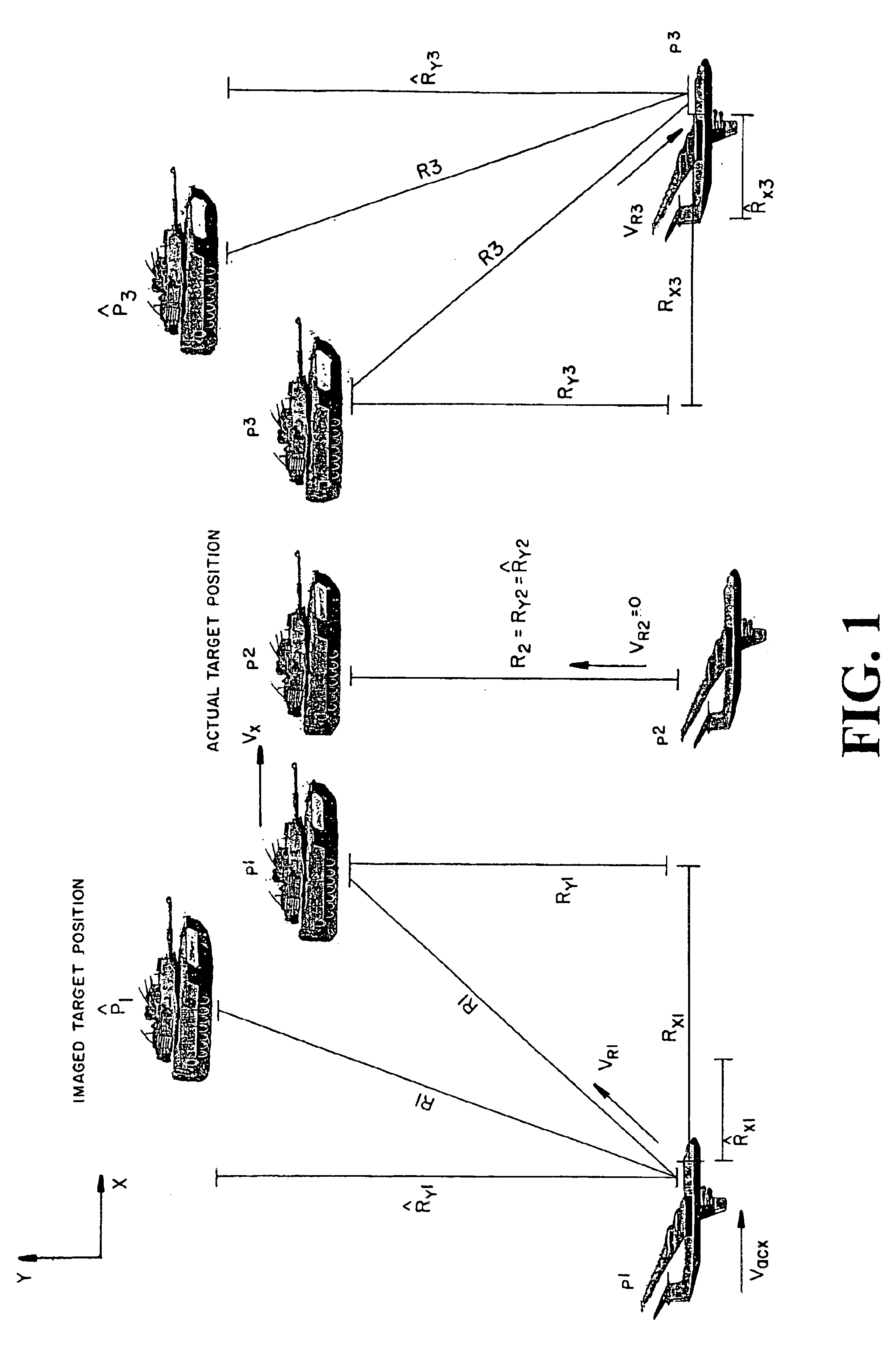
[0032]FIG. 1 is an illustration of SAR image effects of target motion;
[003

Problems solved by technology

However, very slow moving targets like tanks or dismounted troops might be below the minimum detectable velocity (MDV) of GMTI radars.
In synthetic aperture radar (SAR) images, detection of moving targets is difficult because of target smear due to motion, which could make low-RCS targets fall below stationary ground clutter.
Extracting the maximum information from data is possible using adaptive, model-based approaches but in the past such approaches faced prohibitive combinatorial complexity.
Combinatorial complexity is due to the need for having to consider a large number of combinations between multiple target models and the data.

Method used


Image

  • Dynamic logic algorithm used for detecting slow-moving or concealed targets in synthetic aperture radar (SAR) images
  • Dynamic logic algorithm used for detecting slow-moving or concealed targets in synthetic aperture radar (SAR) images
  • Dynamic logic algorithm used for detecting slow-moving or concealed targets in synthetic aperture radar (SAR) images

Examples


example 1

Single Target Detection

[0092]A target is moving with vx=0.5 m / s and has an initial position x0=−6 m, y=3030 m.

[0093]The signal to clutter ratio (SCR) is defined by the maximum absolute value of the target signal and random clutter that is properly scaled. More details on the SCR definition are provided later.

[0094]Detecting more than one target requires adding more models to the algorithm. Similar to the single target case, m=1 represents clutter, m=2 represents target 1, m=3 represents target 2, . . . , m=M represents target M-1. Each target has its own target parameters to be estimated: x0m, y0m and Vxm.

[0095]The probability distribution functions are computed as follows:

[0096]

pdf(n|I)=[r1 r1 . . . ]T, pdf(n⁢2)=⁢∑t=0Np-1⁢ ⁢r2·G2⁡(n,t)⁢for⁢ ⁢the⁢ ⁢1st⁢ ⁢target⁢ ⁢parameters,pdf(n⁢3)=⁢∑t=0Np-1⁢ ⁢r3·G3⁡(n,t)⁢for⁢ ⁢the⁢ ⁢2nd⁢ ⁢target⁢ ⁢parameters,⁢⋮ pdf(n⁢M)=⁢∑t=0Np-1⁢ ⁢rM·GM⁡(n,t)⁢for⁢ ⁢the⁢ ⁢(M-1)th⁢ ⁢target⁢ ⁢parameters,

with the requirement that r1+r2+ . . . +TM=1.

[0097]The total pd...

example 2

[0100]

Target 1Target 2Target 3νx0.3m / s0.4m / s−0.3m / sSCR−0.70dB−1.98dB−0.73dB

[0101]The mutual information functions are individually computed for each target model (Lm) and compared to a threshold. Lm=∑n=1N⁢ ⁢S⁡(n)⁢ln⁡[pdf⁡(n⁢1)+pdf(n⁢m)]⁢ ⁢for⁢ ⁢m=2,3,…⁢ ⁢M L({circumflex over (x)}0,ŷ0,{circumflex over (v)}0)>threshold →target

L({circumflex over (x)}0,ŷ0,{circumflex over (v)}0)>threshold →no target

Performance Analysis

[0102]Receiver operating curves (ROC) were produced in a standard way using simulated clutter. We generated random clutter scenarios in 100×100 pixel images with one meter range and cross-range resolutions. The dynamic logic algorithm was then executed with and without a target signal added to the clutter. This was done using 150 random realizations for several signal-to-clutter ratios.

Simulating Clutter with a Specific Signal to Clutter Ratio

[0103]The performance of the dynamic logic algorithm is evaluated using simulated clutter that is scaled with respect to a simulate...


PUM


Abstract

The present invention includes an application of a dynamic logic algorithm to detect slow moving targets. Show moving targets are going to be moving in the range from 0-5 mph. This could encompass troop movements and vehicles or convoys under rough terrain. The method can be defined as a seven step process of detecting slow moving targets using a synthetic aperture radar (SAR), said slow moving targets being objects of interest that are moving in the range from 0-5 mph, wherein this method is composed of the steps of receiving SAR signal history data having an SAR image; assuming a presence of slow moving target in a SAR image based-on range, cross-range position, and velocity; assuming a presence of clutter; assigning target and clutter models that are probability distribution functions (pdf) that are defined to account for every pixel in the SAR image, wherein the target is modeled using a sum of Gaussians fitted along the target shape model, while the clutter is modeled with a uniform distribution; computing a “target present” predetermined threshold value; converging the target model to a minimum variance value; and comparing the target model minimum variance value to the predetermined threshold to determine if a target is present or absent.

Description

STATEMENT OF GOVERNMENT INTEREST[0001]The invention described herein may be manufactured and used by or for the Government for governmental purposes without the payment of any royalty thereon.BACKGROUND OF THE INVENTION[0002]The present invention relates generally to radar and more specifically to an image processing and target detection process.[0003]Moving targets are usually detected with ground moving target indication (GMTI) radars. However, very slow moving targets like tanks or dismounted troops might be below the minimum detectable velocity (MDV) of GMTI radars. In synthetic aperture radar (SAR) images, detection of moving targets is difficult because of target smear due to motion, which could make low-RCS targets fall below stationary ground clutter. Several techniques for SAR imaging of moving targets have been discussed in the following U.S. Patents, the disclosures of which are incorporated herein by reference:[0004]U.S. Pat. No. 6,300,895, entitled Discreet radar detect...

Claims


Application Information

Patent Timeline
IPC IPC(8): G01S13/90G01S13/00
CPCG01S13/9029G01S13/887
Inventor MUTZ, CHRISTOPHER W.PERLOVSKY, LEONID I.LINNEHAN, ROBERT J.
Owner AIR FORCE GOVERNMENT OF THE US SEC THE
Why Eureka
Eureka Blog
Learn More