Bending beam accelerometer with differential capacitive pickoff

Inactive Publication Date: 2005-07-05
HONEYWELL INT INC
View PDF14 Cites 15 Cited by
  • Summary
  • Abstract
  • Description
  • Claims
  • Application Information

AI Technical Summary

Benefits of technology

[0006]In one aspect of the invention, one or more strain isolation beams are connected between the one or more flexures a

Problems solved by technology

Surviving high shock environments while maintaining performance necessary for navigation purposes imposes significant obstacles on Micro Electro-Mechanical System

Method used


Image

  • Bending beam accelerometer with differential capacitive pickoff
  • Bending beam accelerometer with differential capacitive pickoff
  • Bending beam accelerometer with differential capacitive pickoff

Examples


Embodiment Construction

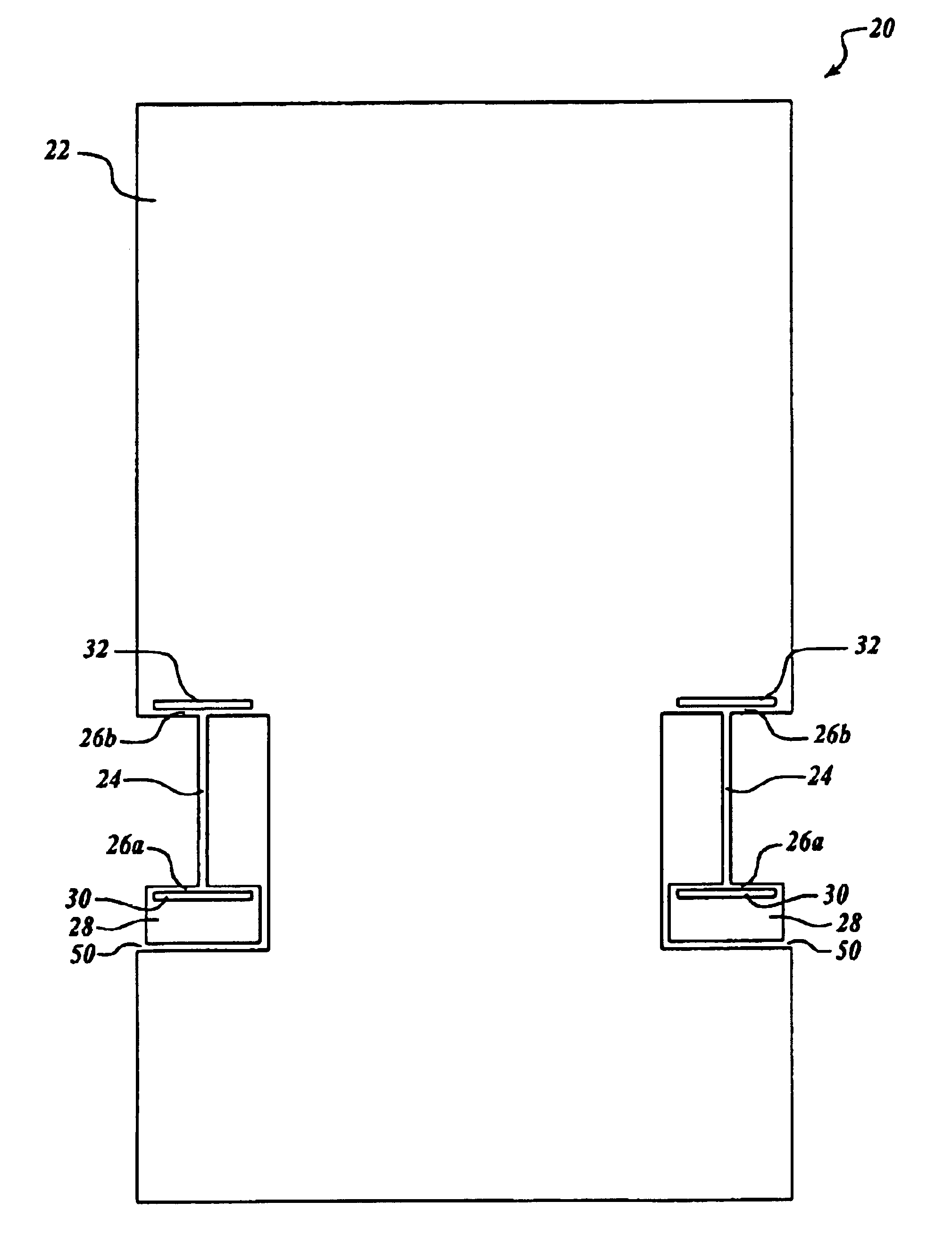
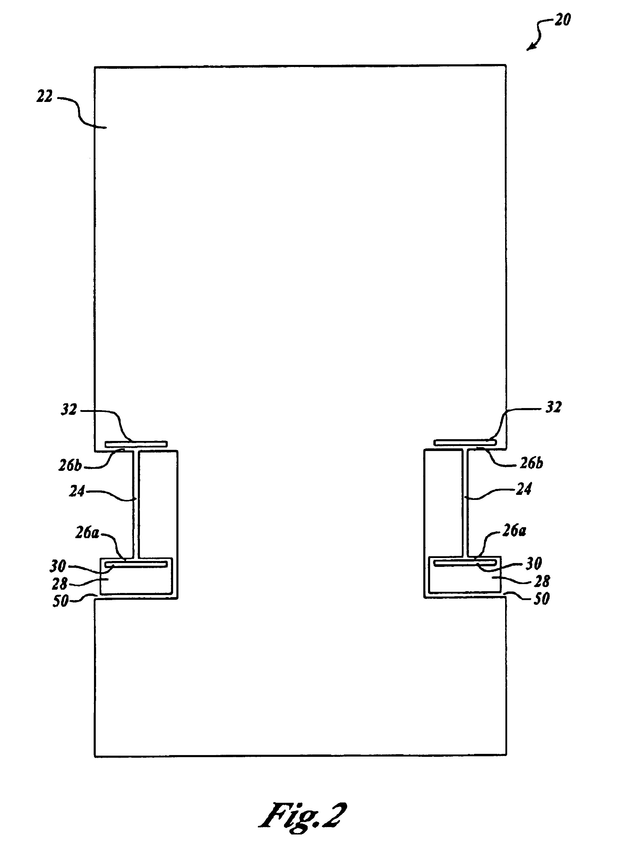
[0011]FIG. 2 illustrates a single axis, pendulous, capacitive-sensing Micro Electro-Mechanical Systems (MEMS) accelerometer 20 formed in accordance with the present invention. The accelerometer 20 includes a pendulous proof mass 22, a pair of cantilever-style flexure beams 24, strain isolation beams 26a and 26b, and securing pads 28. The flexure beams 24 are approximately orthogonally connected at each end to strain isolation beams 26a and 26b. One of the strain isolation beams 26a that is coupled with the flexure beams 24 is attached at its ends to a respective securing pad 28, thereby creating a slot 30 between the beam 26a and the securing pads 28. The securing pads 28 are connected to a housing (not shown) that houses the accelerometer 20. The beam 26b that is connected to the other end of the flexure beam 24 is connected to the pendulous proof mass 22 at each end of the beam 26b, thereby creating a slot 32 between the second beam 26b and the pendulous proof mass 22. Through fle...


PUM


Abstract

A low cost, pendulous, capacitive-sensing Micro Electro-Mechanical Systems (MEMS) accelerometer is provided. The accelerometer includes a pendulous proof mass, one or more securing pads, and one or more flexures coupled with the pendulous proof mass and the one or more securing pads. The flexures flex linearly with respect to motion of the pendulous proof mass. First and second capacitor plates are positioned relative to the pendulous proof mass for detecting motion of the proof mass according to a sensed difference in capacitance. One or more strain isolation beams are connected between the one or more flexures and the pendulous proof mass or the securing pads. The strain isolation beams protect the flexures from mechanical strain.

Description

BACKGROUND OF THE INVENTION[0001]Micro Electro-Mechanical Systems (MEMS) accelerometers typically consist of a pendulous proof mass, a suspension system (flexures) and a method for determining the relative motion of the proof mass under the influence of acceleration (F=MA). Surviving high shock environments while maintaining performance necessary for navigation purposes imposes significant obstacles on Micro Electro-Mechanical Systems (MEMS) accelerometers. Very small MEMS accelerometers are required in order to survive high shock environments. Flexure systems for MEMS accelerometers must be designed to limit motion to a unique sensing axis. The flexure suspension must minimize the effects from environmental stress and strain while possessing enough strength to permit operation in high shock environments. Historically, strain isolation is required on these types of devices to isolate the sensor from mounting strains. The strains experienced are typically due to the thermal coefficie...

Claims


Application Information

Patent Timeline
IPC IPC(8): B81B3/00G01P15/08G01P15/125
CPCB81B3/0072G01P15/08G01P15/125B81B2201/0235G01P2015/0831
Inventor MALAMETZ, DAVID L.BECKA, STEPHEN F.HORNING, ROBERT D.
Owner HONEYWELL INT INC
Why Eureka
Try Eureka