
Tire with composite ply structure and method of manufacture

a composite ply and tire technology, applied in the field of tires with composite ply structure and manufacturing methods, can solve the problems of difficult for tire builder to turn the tire around the beads, difficult for designers to solve difficult challenges, and the ply had to be resolved, so as to improve the contact between the tire and the rim, reduce the indentation of the rim, and ensure the effect of traction

Inactive Publication Date: 2005-07-05
THE GOODYEAR TIRE & RUBBER CO
View PDF6 Cites 28 Cited by
  • Summary
  • Abstract
  • Description
  • Claims
  • Application Information

AI Technical Summary

Benefits of technology

[0015]The present invention provides a method for fabricating a tire utilizing an outside-in ply construction which torques the tire bead into the rim of the wheel to which it is mounted. The tire's outside-in ply construction also serves to pull down the toe of the tire, improving contact between the tire and the rim and to reduce rim indentation. The outside-in ply construction allows the rim to provide greater support for the tire. The increased rim support reduces toe lifting and facilitates the use of a smaller bead as compared to conventional truck tires. A smaller bead, combined with a smaller amount of rubber and reinforcement around and above the bead, reduces the tire's weight and material usage.

Problems solved by technology

As the use of steel cords was first tried in tires some common problems of how to consistently make a ply turnup of a steel cord reinforced ply had to be resolved.
Kovac pointedly notes that if giant cords are used in the carcass, the plies containing them are so stiff that it is difficult for the tire builder to turn them around the beads.
Steel ply turnups have historically provided tire designers very difficult challenges and the use of axially outer steel cord ply turnups generally have required long turnups to insure the folded end stays in place during tire building and subsequent vulcanization.

Method used


Image

  • Tire with composite ply structure and method of manufacture
  • Tire with composite ply structure and method of manufacture
  • Tire with composite ply structure and method of manufacture

Examples


Embodiment Construction

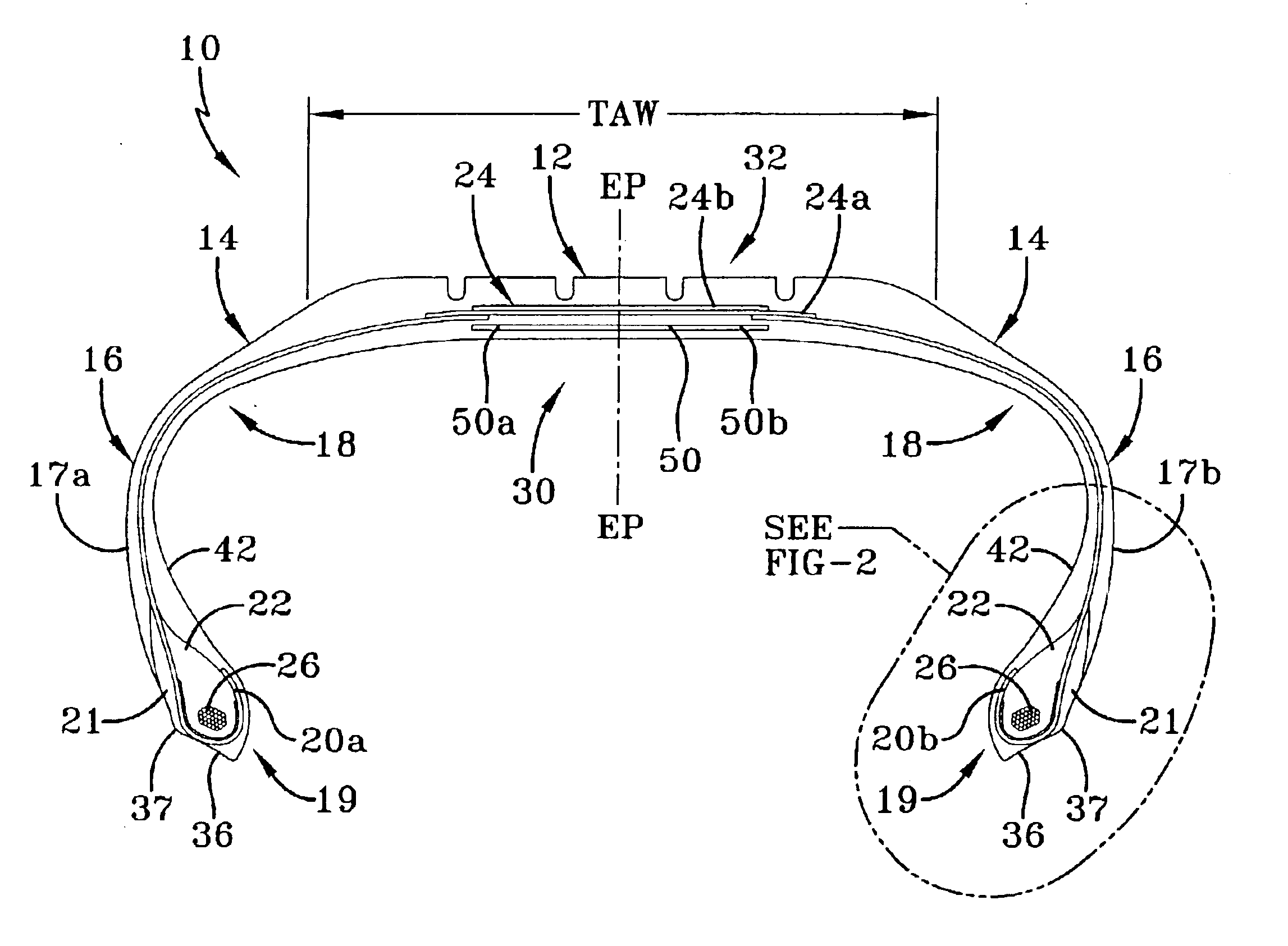
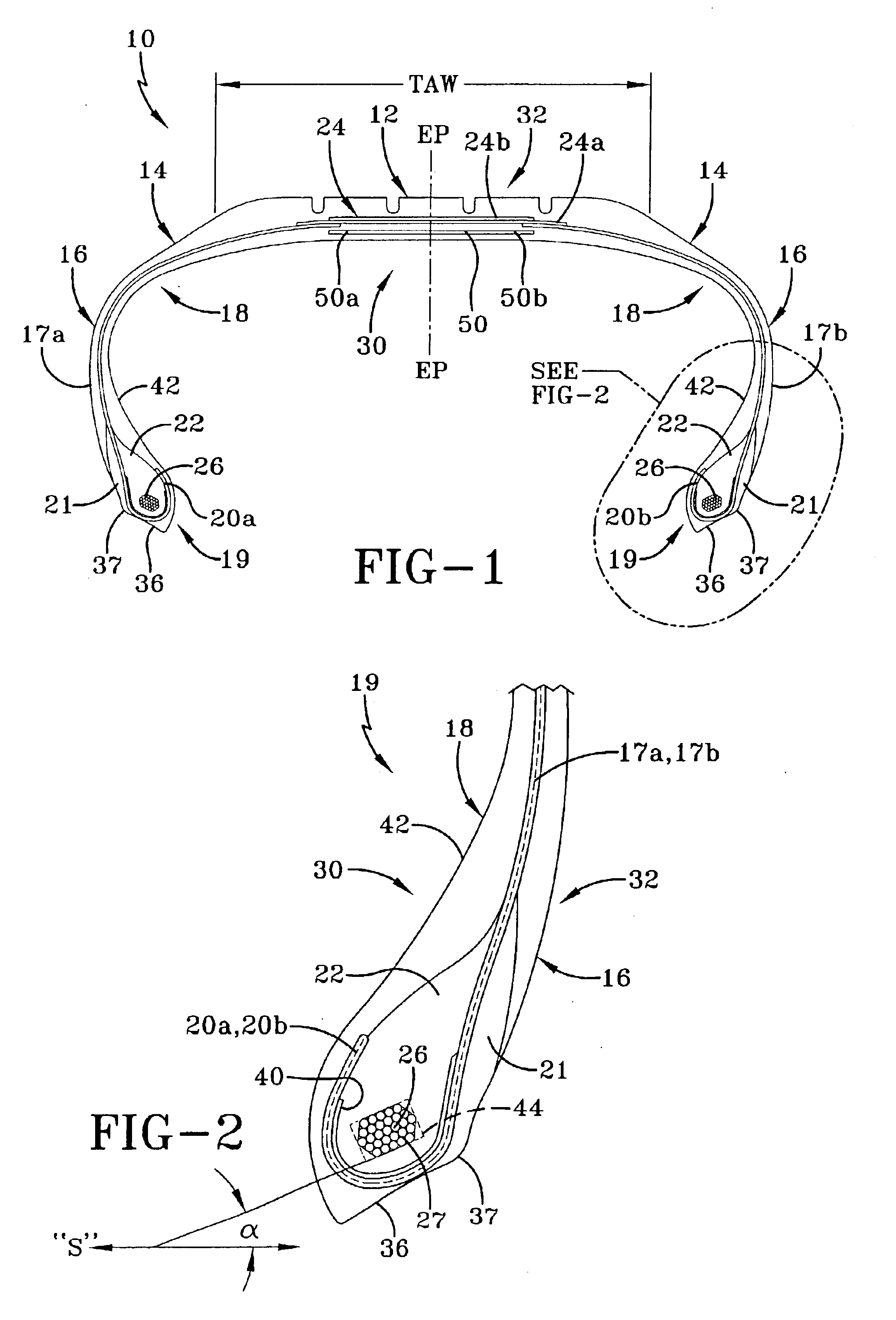
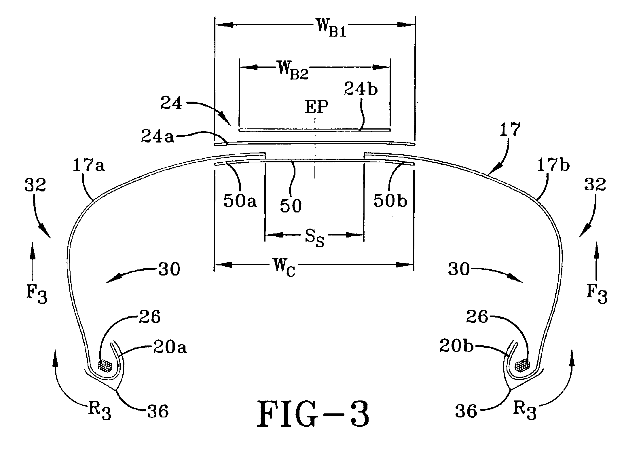
[0056]In the drawings the same numbers are used for the same components or items in the several views. With particular reference to FIG. 6, there is illustrated a cross-sectional view of the general construction of a prior art tire 100. The tire has a tread portion 12 and a pair of sidewalls 16 wherein the sidewalls are connected to the tread portion by shoulder regions 14. The tire may have one or more reinforcing belts 24. A carcass 18 of the tire includes one or more continuous radial plies 15, such as steel radial plies, extending from side to side. Bead regions 19 of the tire have a pair of axially spaced bead cores 26 around which are wrapped turn-up ends 20 of the radial plies 15. An apex 22 is sandwiched between the main body of the carcass 18 and the turn-up ends 20. Toes 36 and heels 37 provide a base for fitting the tire 100 to a wheel rim (not shown). FIG. 6 also illustrates the equatorial plane (“EP”) and the tread arc width (“TAW”) of the tire 100.

[0057]FIG. 7 illustra...


PUM

PropertyMeasurementUnit
pressureaaaaaaaaaa
cord anglesaaaaaaaaaa

Abstract

The tire construction and method of building a tire 10 comprises the steps of cylindrically applying a pair of radial cord reinforced sidewall plies 17a, 17b, fixing the axial spacing between the bead cores; applying a crown ply 50, turning up each sidewall ply 17a and 17b to overlap lateral edges of the crown ply 50; moving the carcass assembly 18 axially inwardly while shaping the carcass assembly 18 toroidially to form ply turnups 20a, 20b axially inwardly of the bead cores 26. The method further comprises the steps of applying one or more belt reinforcing layers to the carcass and first reinforcing layer and applying a tread to form a pneumatic radial ply tread tire.

Description

RELATED APPLICATIONS[0001]This patent application is a continuation-in-part of and claims priority to U.S. Ser. No. 10 / 330,890, filed on Dec. 27, 2002, entitled “Tire With Outside-In Ply Construction”.[0002]This invention relates to tires generally and more specifically to tires having a composite ply structure including at least two split plies of inextensible radial extending cords, most preferably of steel cords primarily for use in pneumatic truck tires having axially inner ply turnups, and a method of manufacturing such a tire.BACKGROUND OF THE INVENTION[0003]The use of radial steel cords in tires is well known in the tire art, earthmover and commercial truck tires have used steel corded tires for years.[0004]As the use of steel cords was first tried in tires some common problems of how to consistently make a ply turnup of a steel cord reinforced ply had to be resolved.[0005]Historically one must first ask the question of whether or not a ply turnup is even needed.[0006]In 1921...

Claims


Application Information

Patent Timeline
Patent Type & Authority Patents(United States)
IPC IPC(8): B60C9/04B60C9/08B29D30/20B60C15/00
CPCB29D30/20B60C9/08B60C15/0072B60C9/0207B60C15/0018B29D2030/086Y10T152/10819Y10T152/10837
Inventor LOSEY, ROBERT ALLEN
Owner THE GOODYEAR TIRE & RUBBER CO
Learn More