Welding wire container with ribbed walls and a mating retainer ring

a technology of retaining ring and welding wire, which is applied in the direction of tray containers, manufacturing tools, transportation and packaging, etc., can solve the problems of reducing production yield, adversely affecting the welding process, and shutting down an entire manufacturing line, so as to prevent convolution, reduce manufacturing costs, and reduce the effect of ring jamming

Inactive Publication Date: 2005-07-05
LINCOLN GLOBAL INC
View PDF28 Cites 53 Cited by
  • Summary
  • Abstract
  • Description
  • Claims
  • Application Information

AI Technical Summary

Benefits of technology

[0024]Still another object is a provision of a welding wire package of the foregoing character which can be lightweight and disposable.
[0025]A further object is the provision of a welding wire package of the foregoing character which minimizes ring jamming while also preventing the convolutions of the wire coil from escaping beyond the outer peripheral edge of the retainer ring without the need of frictional interengagement with the inner surface of the outer container.
[0026]Yet a further object is the provision of a welding wire package of the foregoing character wherein an existing outer package can easily be converted to a ribbed package design according to the present invention.
[0027]Another object is the provision of a welding wire package of the foregoing character which utilizes components that are economical to manufacture, easy to use in the field and protect the welding wire.

Problems solved by technology

Furthermore, welding applications wherein large quantities of welding wire are consumed necessitate welding wire packages which contain large quantities of a continuous welding wire.
Each tangle can potentially shut down an entire manufacturing line and reduces production yield.
It is well known that wire has a tendency to seek a predetermined natural condition which can adversely affect the welding process.
While reel packaging has a low tendency of tangling, it can occupy a large amount of floor space and is not easily changed over due to the time necessary to set up the dereeler equipment.
Furthermore, the welding wire on the reel is exposed to the environment of the manufacturing operation which is often dusty and / or dirty.
Another disadvantage of the reel type container is that they must be a rigid structure to hold the weight of the wire and allow the wire to pivot about an axis.
As a result, disposing of the spent wire reel is costly.
Furthermore, abuse during shipping and handling of the soft drum or box container often disrupts the uniform spacing or stacking of each convolution in the wire stack.
Therefore, while drum or box wire packages provide some advantages over reeled wire, they are more susceptible to tangling.
However, when the welding wire is dispensed from the package, the walls of the package lose their influence on the wire and the wire will attempt to assume its natural cast.
This causes the portion of the wire which is being withdrawn from the package to loosen and tend to spring back into the package thereby interfering and possibly becoming tangled with other convolutions of wire.
For one, if the retainer ring becomes misaligned with respect to the drum wall it can become jammed with the packaging.
Another problem with this design is that due to the minimal clearance between the ring and the drum, the drum outer wall must be nearly a perfect cylinder or the retainer ring can become lodged by the imperfections.
Imperfections in the drum outer wall can be caused by a manufacturing problem or damage during the shipment of the welding wire package.
Furthermore, shrink wrapping the drum for the shipment can also cause distortions in the outer wall of the drum.
As a result, the low clearance ring design causes a large amount of down time necessary to continuously free a jammed or hung-up ring.
As a result, the wire convolutions can pop upwardly between the outer periphery of the retainer ring and the drum wall which can severely tangle the welding wire and cause significant down time.
This condition is worsened by the fact that the welding wire, which is pulled from the center of the retaining ring, has a tendency to urge one side of the retainer ring outwardly against the drum wall.
This shifting enlarges the gap along the back side of the retainer ring disadvantageously increasing the likelihood that one or more convolutions of wire may spring upwardly through the gap.
This condition is called “back side tangle” and can damage the retainer ring.
As can be appreciated, a damaged retainer ring which is tangled amongst several convolutions of wire can cause significant down time.
However, the frictional engagement between the retainer ring and the inner container walls, introduced drag into the system which adversely reduces the downward force produced by the retainer ring.
The drag produced by the flexible members can also adversely jam the retainer ring above the wire coil, thereby reducing its control on the wire payout.
Furthermore, this ring design is still influenced by imperfections or damage to the outer drum of the wire package.
Further, the flexible members can break or crack causing tangling of the welding wire.
While rigid package designs can be used to reduce the likelihood of shipping damage, reduce coil shifting during shipment, and enhance the stackability of the package, rigid packages are difficult and expensive to dispose of.

Method used


Image

  • Welding wire container with ribbed walls and a mating retainer ring
  • Welding wire container with ribbed walls and a mating retainer ring
  • Welding wire container with ribbed walls and a mating retainer ring

Examples


Embodiment Construction

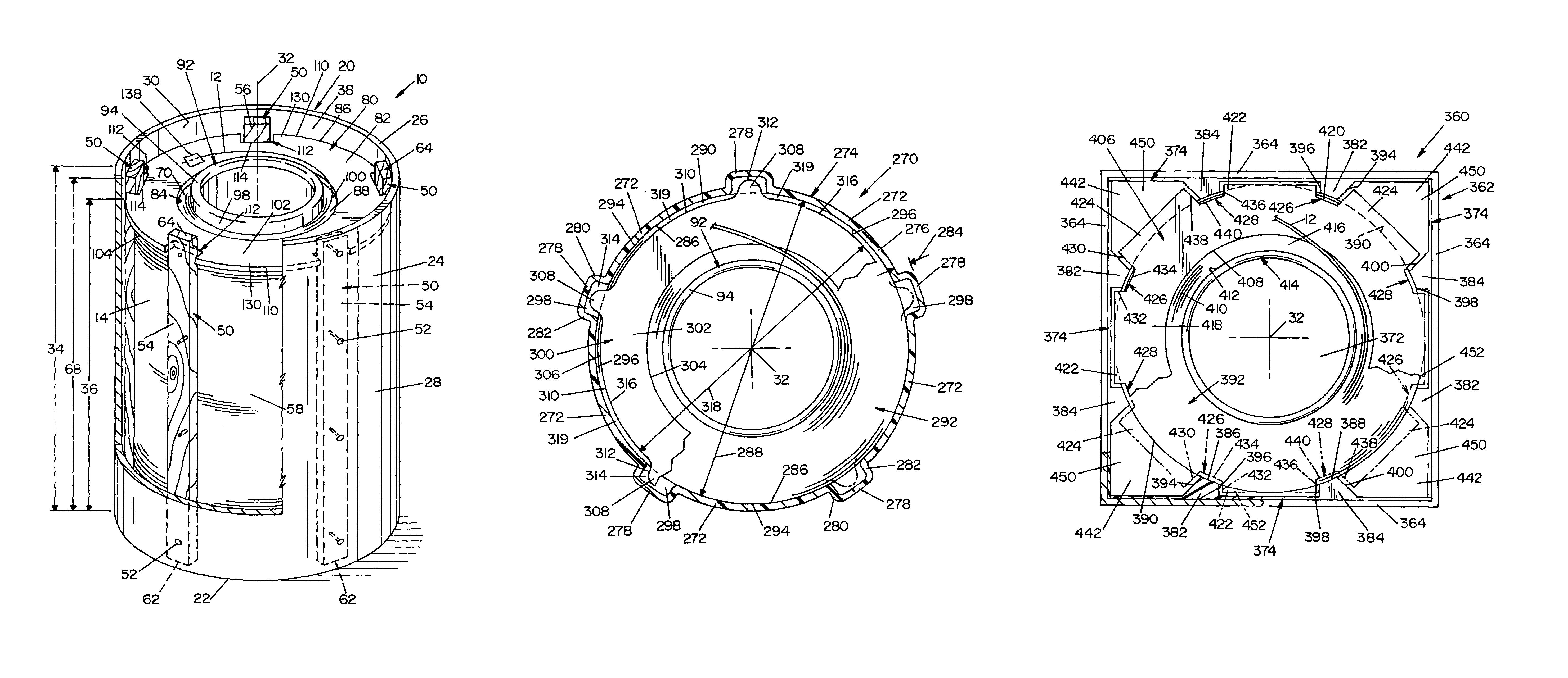
[0043]Referring now in greater detail to the drawings wherein the showings are for the purpose of illustrating preferred embodiments of the invention only, and not for the purpose of limiting the invention, FIGS. 1 and 2 show a welding wire package 10 for containing and dispensing a continuous wire 12 of a wire coil 14. Package 10 includes a drum style carton or container 20 having a bottom 22 and a single outer wall 24 extending from bottom 22 to a top edge 26. As can be appreciated, drum 20 can be any type of drum know in the industry including fiber drums, plastic drums and / or sheet metal drums. Outer wall 24 has an outwardly facing surface 28 and an inwardly facing surface 30 and is substantially coaxial to a coil axis 32. Drum 20 is preferably a cardboard drum, however, the drum can be made from any suitable material known in the art. Outer wall 24 has a height 34 which is slightly greater than coil height 36. Drum 20 is shaped to receive wire coil 14 in a coil receiving recess...


PUM

PropertyMeasurementUnit
flexibleaaaaaaaaaa
weightaaaaaaaaaa
stableaaaaaaaaaa

Abstract

A package for containing and dispensing a coil of welding wire having a coil axis parallel to a package axis, a coil top transverse to the coil axis and radially inner and outer surfaces parallel to the coil axis. The welding wire package includes a container having a bottom and an outer wall structure extending upwardly from the bottom to a top edge, and the outer wall structure has inwardly and outwardly facing surfaces. The package further includes a plurality of ribs extending parallel to the package axis and positioned between the coil outer surface and the inwardly facing surface of the outer wall structure thereby forming gaps between the coil outer surface and the inwardly facing container surface. The welding wire package further including a retainer ring for controlling the dispensing of the welding wire. The retainer ring includes a ring body extending between an inner edge defining an inner opening and an outer peripheral edge, and the outer peripheral edge includes a plurality of projections each extending beyond the outer surface of the wire coil and over a portion of the gaps.

Description

[0001]This invention relates to the art of dispensing wire and, more particularly, to a ribbed package for containing and dispensing large quantities of a continuous wire without tangling.INCORPORATION BY REFERENCE[0002]The present invention relates to feeding large quantities of a continuous wire from a container to a welding operation wherein the wire must be fed to the welding operation without tangling or interruption. Such containers are known in the art and are generally shown and described in Cooper U.S. Pat. No. 5,277,314; Cooper U.S. Pat. No. 5,819,934; Kawasaki U.S. Pat. No. 4,869,367; and Gelmetti U.S. Pat. No. 5,494,160. These patents are incorporated by reference herein as background information illustrating packages for containing and dispensing large quantities of wire. Further, these patents illustrate the importance of controlling the wire as it is being dispensed from the package to prevent tangling.[0003]Seufer U.S. Pat. No. 5,816,466 illustrates the interaction b...

Claims


Application Information

Patent Timeline
Patent Type & Authority Patents(United States)
IPC IPC(8): B23K9/133B65H49/00B65H49/08
CPCB65H49/08B23K9/1333
Inventor BARTON, DAVID J.HSU, CHRISTOPHER
Owner LINCOLN GLOBAL INC
Why Eureka
Try Eureka