Lightweight collapsible reel for cable, conduit or tubing

a technology of collapsible reels and cables, applied in the field of lightweight collapsible reels, can solve the problems of not revealing or suggesting a collapsible lay flat reel, and achieve the effects of reducing the number of cables

Inactive Publication Date: 2005-07-05
DIRECT WIRE & CABLE
View PDF3 Cites 9 Cited by
  • Summary
  • Abstract
  • Description
  • Claims
  • Application Information

AI Technical Summary

Benefits of technology

[0007]The present invention provides a lightweight, collapsible reel for cable, conduit or tubing in which a pair of opposed, relatively thin, generally circular, coaxially end flanges of substantially equal diameter are interconnected by at least three foldable cable, conduit or tubing support units. The reel, when fully collapsed, is no thicker than twice the thickness of each individual end flange. The support units, which each include a pair of hingedly interconnected end-to-end leg segments that cooperate in their fully extended, straight-line positions, to present a generally triangular cage internal of the space between the flanges for wrapping of cable, conduit, tubing or the like around the support units.
[0010]The leg segments of the support units are preferably molded to define a series of elongated, side by side ribs which increase the beam strength of the individual segments while saving weight. The flanges are provided with a series of elongated recesses located to complementally receive the rib portions of respective leg segments of the support units. When the reel is collapsed by folding of the support units, the rib portions of the leg segments of each support unit, which face outwardly relatively, are fully received in respective recesses in the flanges so that the inner faces of the flanges move into interengaging, side by side relationship. The result is a reel when collapsed that is no thicker than the thickness of the side by side flanges.
[0014]An important advantage of the present collapsible reel is the fact that manufacture of the reel of synthetic resin material as explained permits recycling of the reel at the end of its useful life, which in most instances should be at least the order of fifty cycles of use. Another advantage is the minimal thickness of a fully collapsed reel, which is ⅙th to {fraction (1 / 7)}th that of a conventional reel. The no more than 2× flange thickness of each collapsed reel results in significant savings in return transportation costs of empty reels in collapsed condition from a space standpoint, in that a significantly larger number of reels may be transported in the space that would have been taken up in the transport vehicle by conventional reels. In addition, minimization of warehousing space required for empty reels provides significant cost savings. The collapsed reels are much easier to handle and maneuver because of the decreased weight as compared with conventional plywood reels.

Problems solved by technology

Thus, Brown in the '606 patent does not disclose or suggest a collapsible lay flat reel.

Method used


Image

  • Lightweight collapsible reel for cable, conduit or tubing
  • Lightweight collapsible reel for cable, conduit or tubing
  • Lightweight collapsible reel for cable, conduit or tubing

Examples


Embodiment Construction

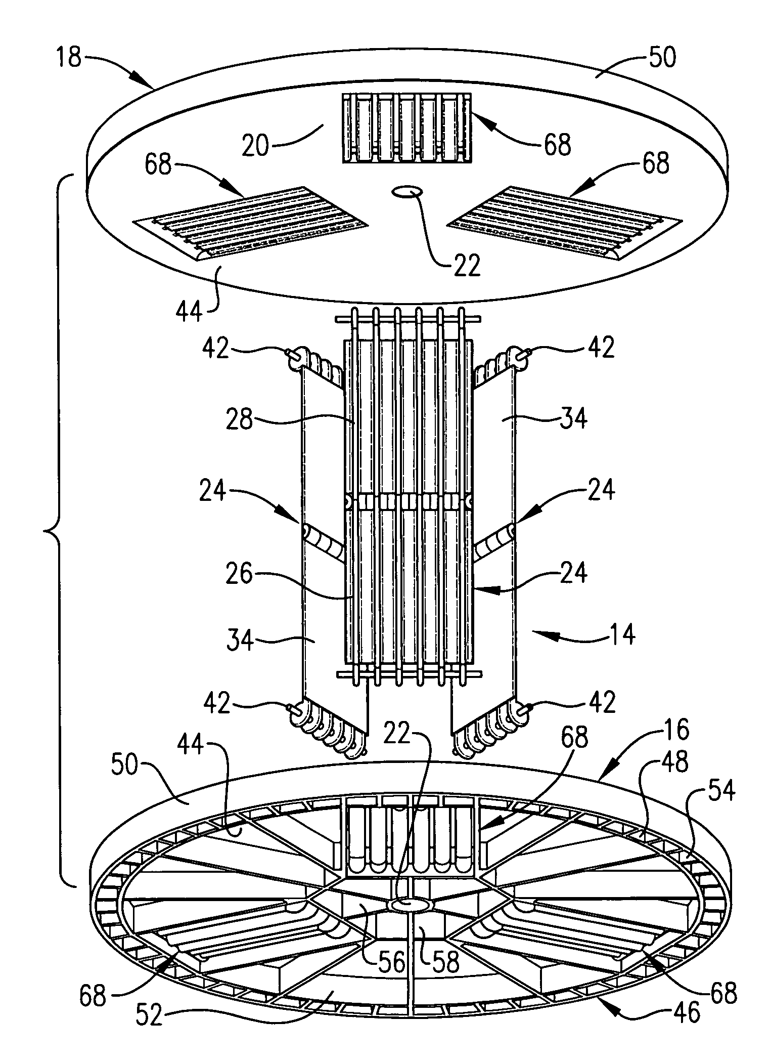
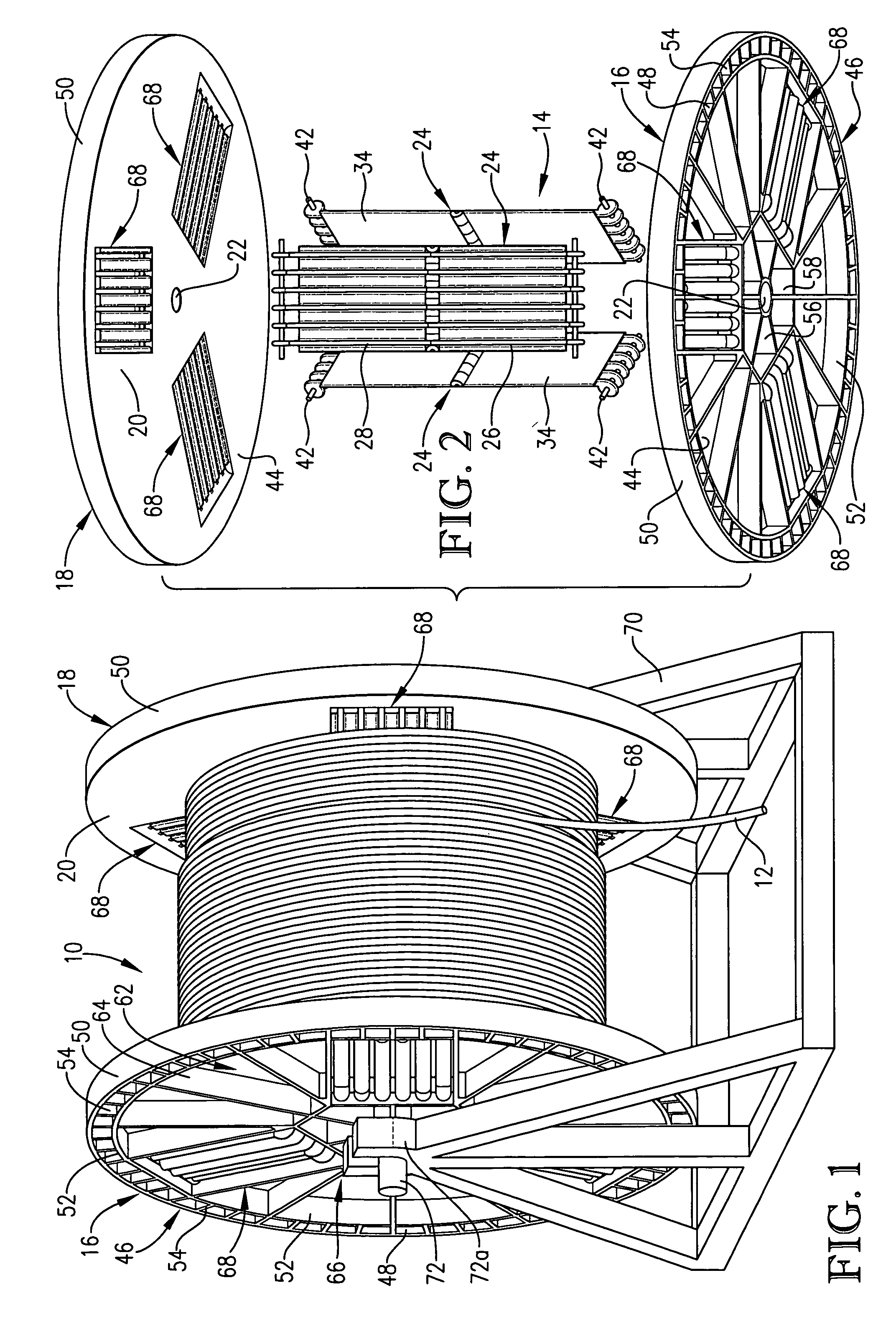
[0028]The collapsible reel, broadly designated by the numeral 10 in the drawings, is especially adapted in its expanded condition, as shown in FIG. 1 of the drawings to support cable, conduit or tubing 12 or the like wrapped around the central cage defining structure, designated by the numeral 14 in FIG. 2. Reel 10 includes two opposed, relatively thin, identical, generally circular, oppositely oriented, coaxially positioned end flanges 16 and 18.

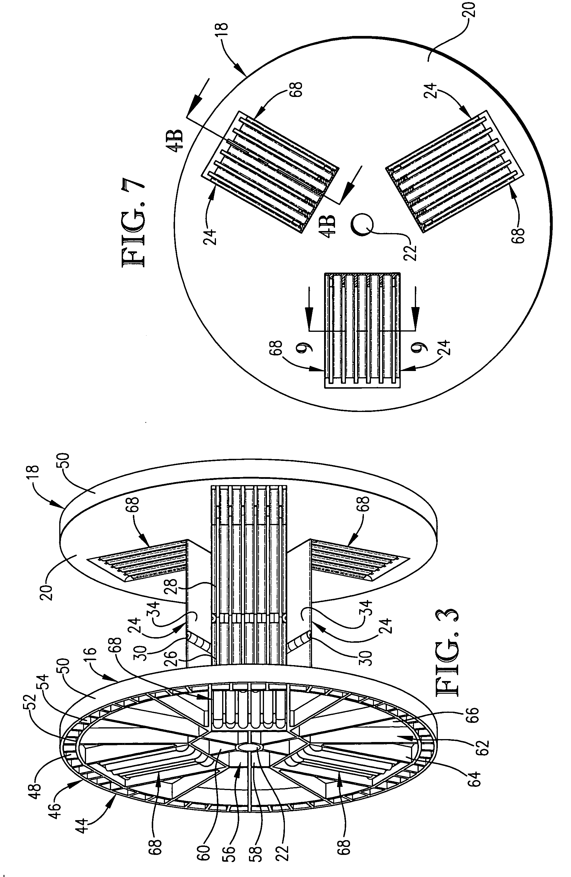
[0029]For simplicity, in view of the identical nature of flanges 16 and 18, the same component parts of each of the flanges 16 and 18 are given the same number in the drawings. Thus, as is apparent from FIGS. 1 and 2, each of the circular end flanges 16 and 18 has an inner, relatively flat face 20 provided with a circular guide rod or pipe opening 22 in the center thereof.

[0030]Three foldable cable, conduit or tubing support units 24 are hingedly connected to opposed inner faces 20 of end flanges 16 and 18. Each support unit 24 includes a p...


PUM


Abstract

A lightweight, collapsible, readily repairable, minimum thickness reel for cable, conduit, tubing or the like and the components of which are preferably molded of synthetic resin material. The end flanges of the reel each have a flat inner surface and a cellular outer surface for decreased weight. Molded, foldable ribbed tubing support units are interposed between the inner surfaces of the end flanges for receiving and supporting cable, conduit or tubing wound therearound when the support units are extended. The planar, inner surfaces of the end flanges have recesses for complementally receiving the rib portions of the leg segments of respective support units so that when the reel is in its collapsed condition the reel is not substantially thicker than the combined thickness of the side by side end flanges. The end flanges are molded of a synthetic resin material in a mold which receives pre-molded leg segments with a release agent thereon which results in concomitant forming of the recesses for the folding leg segments of the support units. A blowing agent may be incorporated in the resin in which the flanges are molded so that a relatively thin, tough, abrasion resistant skin is formed while the interior of the wall structure of the flange is of decreased density.

Description

BACKGROUND OF THE INVENTION[0001]1. Field of the Invention[0002]This invention relates to a lightweight, collapsible reel for supporting cable, conduit or tubing wound therearound and especially to a reel collapsible to a thickness no greater than approximately the thickness of the two side by side circular end flanges of the reel. The components of the reel are especially adapted for fabrication of synthetic resin material which results in an extremely lightweight reel that retains its load bearing properties and characteristics after repeated in-field use of individual reels.[0003]Collapsible reels for supporting products such as elongated stretches of a cable, conduit or tubing wound around the core of the reel are known but have not heretofore gained widespread recognition in the field. Although deficiencies in marketing of past collapsible reels may have been a contributing factor in limited customer demand for prior reels, the inability of such reels to fully collapse and the ...

Claims


Application Information

Patent Timeline
Patent Type & Authority Patents(United States)
IPC IPC(8): B65H75/22B65H75/24B65H75/18
CPCB65H75/22B65H2701/5136B65H75/2254B65H75/2227B65H75/2209
Inventor MAXWELL, DONALD J.VOSSEN, DAVID
Owner DIRECT WIRE & CABLE
Why Eureka
Try Eureka