
Board anchor

a technology for anchoring boards and boards, applied in the direction of screws, constructions, fastening means, etc., can solve the problems of inability to anchor boards to hollow walls, inability to operate with ease, and work efficiency decline, and achieve the effect of convenient installation

Inactive Publication Date: 2005-07-05
KOYOKIZAI
View PDF10 Cites 8 Cited by
  • Summary
  • Abstract
  • Description
  • Claims
  • Application Information

AI Technical Summary

Benefits of technology

[0009]In this manner, because the freely rotating anchor section is attached to the screw shaft via an attachment material, the screw shaft and the anchor section can both be inserted through the hole by positioning them in a straight line, thus making it unnecessary to work from both sides of the wall. Therefore, the anchoring of the board can be done from one side of the wall and the board can be anchored even if the wall is hollow. Since the work is done on one side of the wall, one person is able to anchor the board, thus, enhancing operability and work efficiency.
[0019]The present invention thus provides a board anchor whereby one person can anchor the board, enhancing installation operability and work efficiency. The connection provided by the board anchor of the present invention is strong and can be used with boards and walls of various thicknesses.

Problems solved by technology

Therefore, if the wall is hollow, one can work only on one side of the wall, thus making it impossible to anchor the board to a hollow wall.
Also, it is difficult for one person to work on both sides of the wall, causing problems in terms of operational ease.
Moreover, work efficiency declines if more than one worker is required to anchor a board.

Method used


Image

  • Board anchor
  • Board anchor
  • Board anchor

Examples


Embodiment Construction

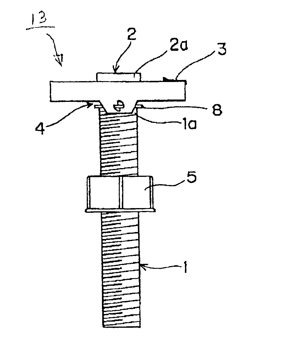
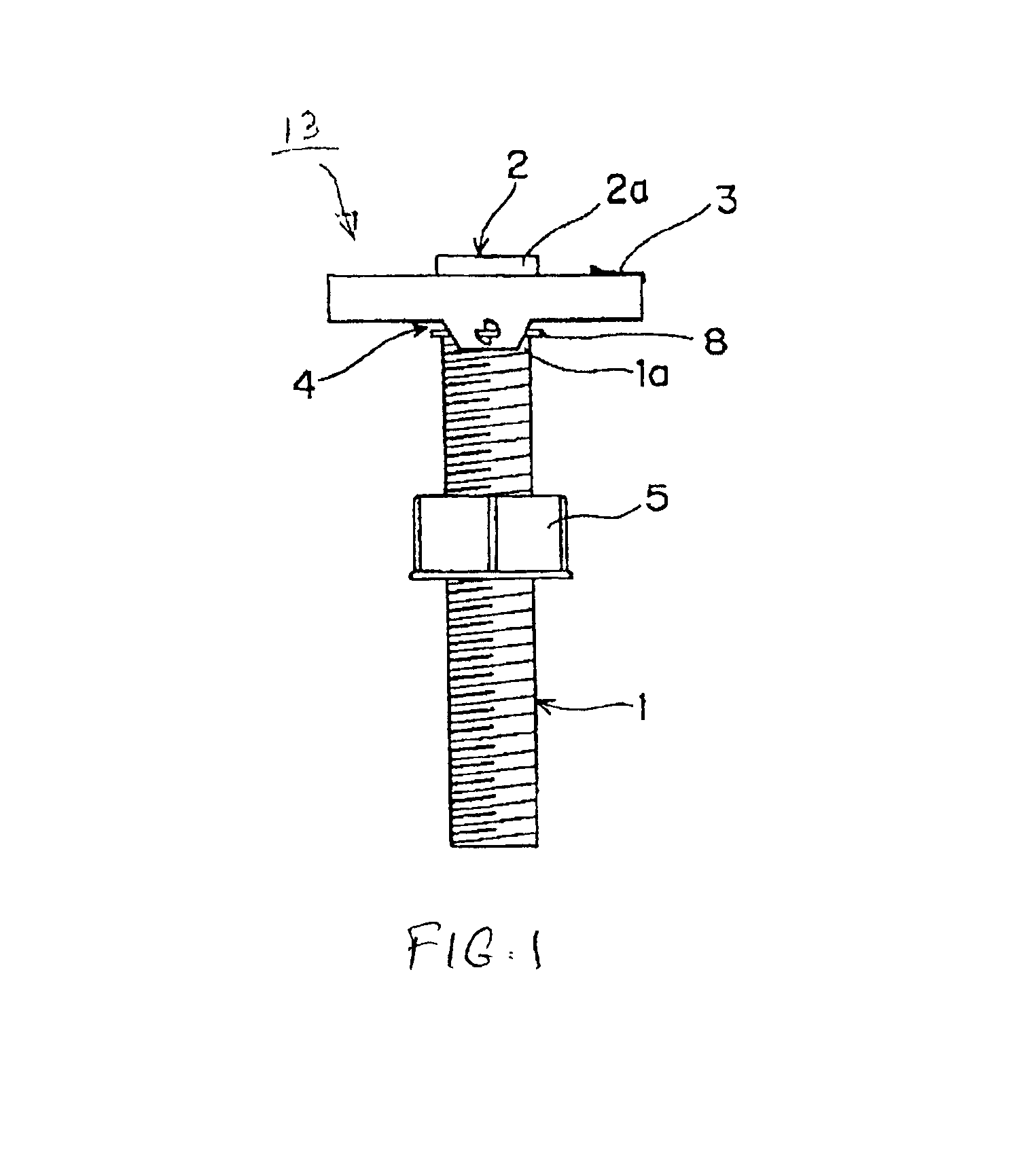
[0025]Referring now to FIG. 1, the anchor board device 13 of the present invention is illustrated. Anchor board device 13 is used to anchor board 21 to wall 11 (FIG. 7).

[0026]Anchor board 13 is equipped with screw shaft 1, freely movable, rectangular shaped anchor section 2 connected via attachment ring 8 to screw shaft 1, plate spring 3, (a pressure device that re-positions anchor section 2 to a 90 degree crosswise position to screw shaft 1 from a position parallel with the shaft), and stopper mechanism 4 which stops the anchor section 2 at the cross position. Attachment ring 8 is screwed onto end section la of screw shaft 1. A ring washer 5 is installed on the outer circumference of screw shaft 1 with freedom of movement along the screw and functions as a bushing.

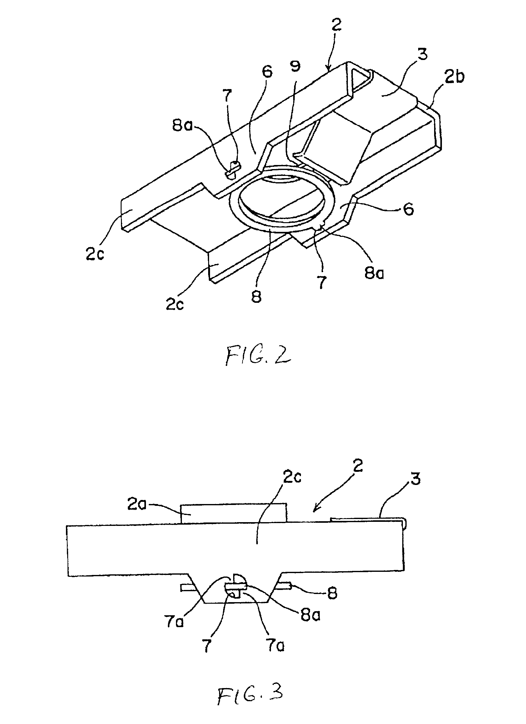
[0027]Anchor section 2 has screw section 2a where screw shaft 1 is inserted. As shown in FIG. 2, screw section 2a of anchor section 2 forms screw hole 9 that fits screw shaft 1 in an open position. Also, end section 2b of...


PUM


Abstract

A board anchor comprising a screw shaft, freely rotating anchor section attached to the screw shaft via a spring and stop attachment for re-positioning the anchor section in a crosswise position against the screw shaft from a position parallel with the screw shaft, a stopper mechanism that stops the above screw shaft in the above cross position, and an attachment ring that screws onto the screw shaft, with the anchor section having a screw hole which fits the screw in the above upright position.

Description

BACKGROUND OF THE INVENTION[0001]1. Field of the Invention[0002]The present invention provides a board anchor for affixing an object to a wall or board.[0003]2. Description of the Prior Art[0004]Conventional prior art board anchors consist of a shaft section, an anchor section affixed to one edge of the shaft and a screw section formed at the other end of the shaft. When affixing an object to a board, the shaft section is inserted through a hole bored through one side of a wall, while the anchor section is in flush contact with the wall. On the other side of the wall, the board is placed against the wall so that the shaft is inserted into the screw hole in the board, and the board is pressed and anchored to the wall by tightening a nut attached to the screw section.[0005]In the conventional board anchor, it is necessary to work from both sides of the wall to anchor the board to the wall. Therefore, if the wall is hollow, one can work only on one side of the wall, thus making it impo...

Claims


Application Information

Patent Timeline
Patent Type & Authority Patents(United States)
IPC IPC(8): F16B13/08F16B13/04E04B1/48E04B1/38F16B35/04
CPCF16B13/0808
Inventor ITO, KATSUO
Owner KOYOKIZAI
Learn More