Process for anchoring connecting elements in a material with pores or cavities and connecting elements therefor

a technology of pores or cavities and connecting elements, which is applied in the direction of furniture joining, dowels, lamination, etc., can solve the problems of weakening or even destroying the join

Inactive Publication Date: 2005-07-05
WOODWELDING
View PDF112 Cites 205 Cited by
  • Summary
  • Abstract
  • Description
  • Claims
  • Application Information

AI Technical Summary

Benefits of technology

[0016]The attainable depth of the anchoring of a synthetic material in a porous material is dependent on its structure (e.g., for wood on the density of the wood fibers), but also on the pressure applied and the locally available plasticized material quantity. As will be shown hereinafter, in solid wood, e.g., anchoring depths of 1 to 4 cm are readily attainable.

Problems solved by technology

The above methods have many of the same disadvantages as bonding methods, particularly their sensitivity to moisture and thermal stresses in which the two joined-together surfaces expand to varying degrees and considerable shear forces arise which weaken or even destroy the joint.

Method used


Image

  • Process for anchoring connecting elements in a material with pores or cavities and connecting elements therefor
  • Process for anchoring connecting elements in a material with pores or cavities and connecting elements therefor
  • Process for anchoring connecting elements in a material with pores or cavities and connecting elements therefor

Examples


Embodiment Construction

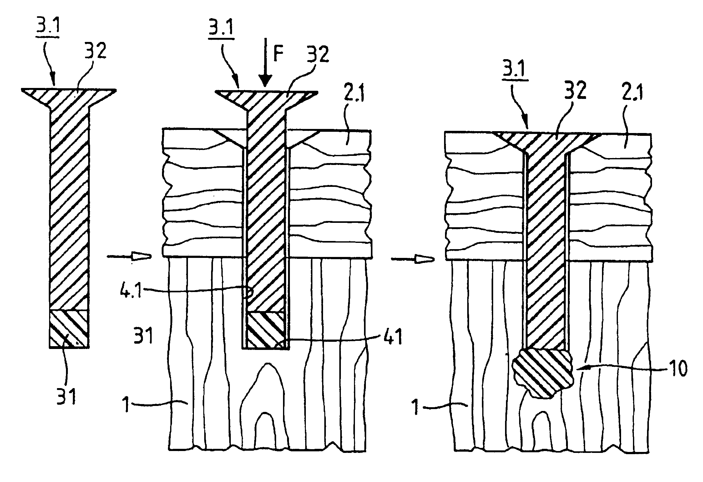
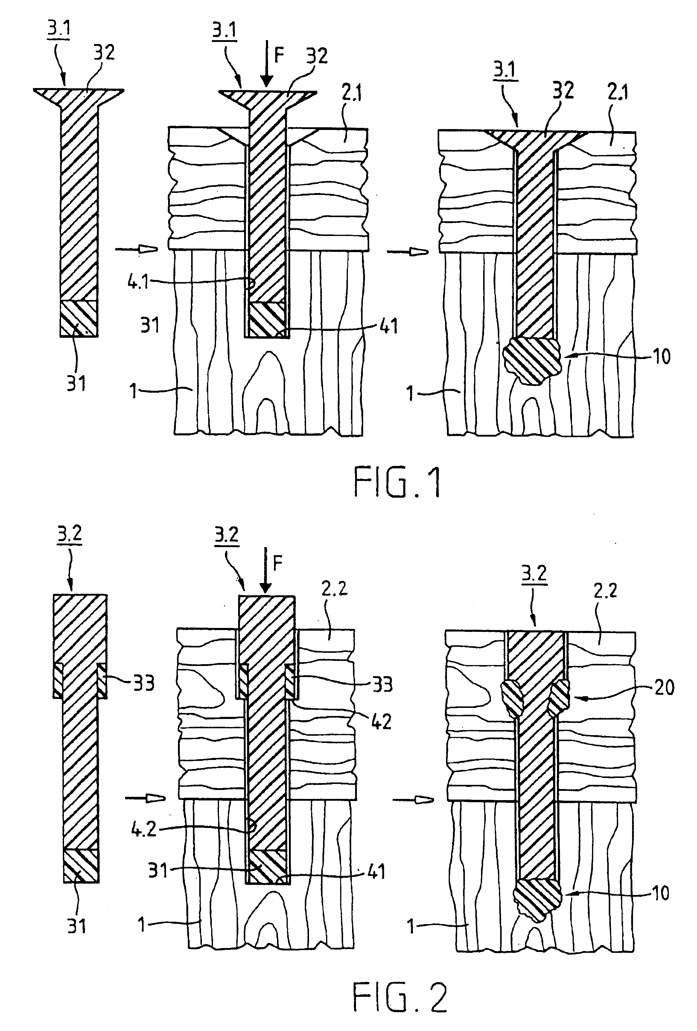
[0027]FIG. 1 shows a first embodiment of the inventive method which involves anchoring a pin-like joining element 3.1 with a head 32 in a first, wooden part 1 for joining first part 1 to a second part 2.1, which is, e.g., also made from wood.

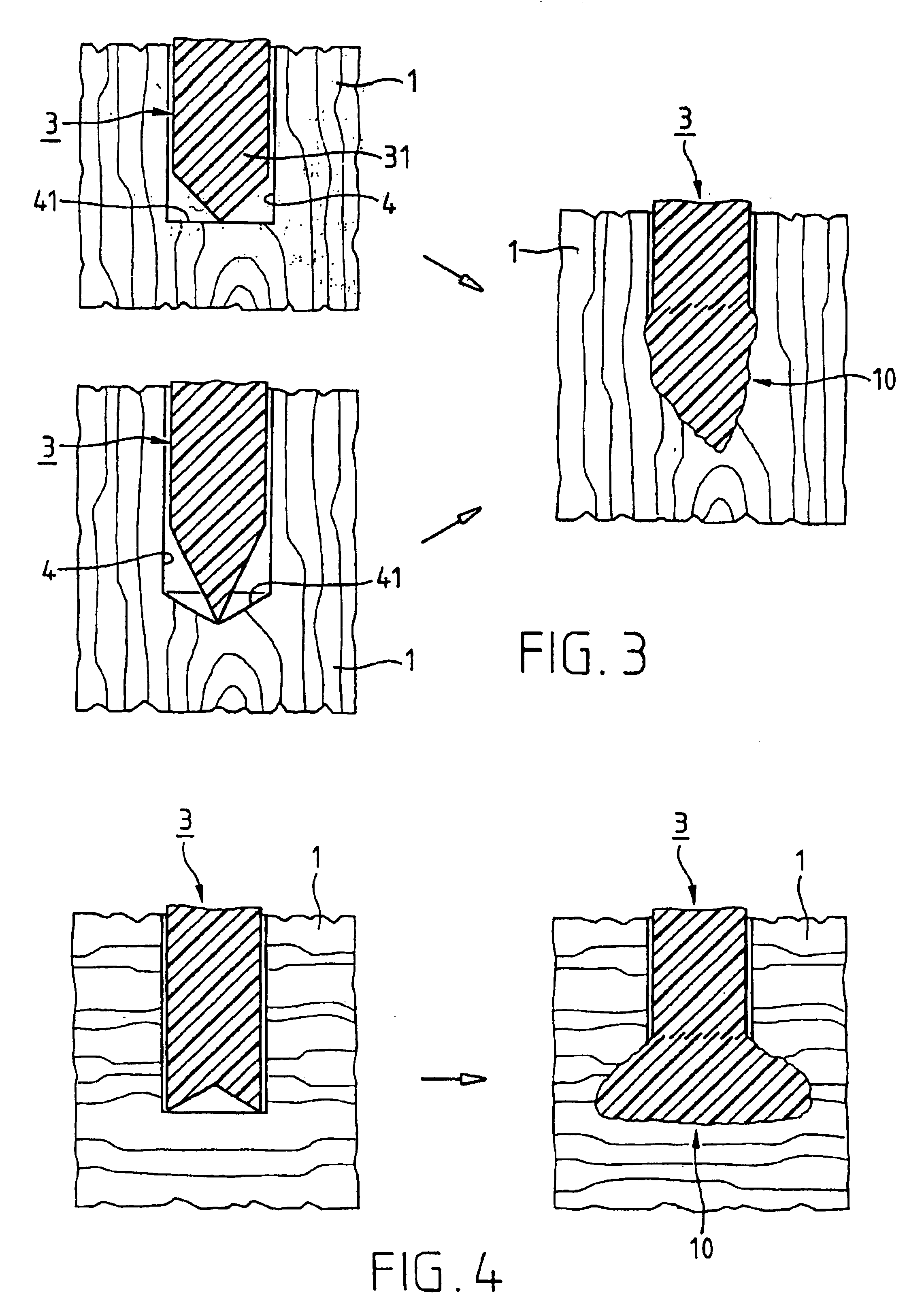
[0028]In the vicinity of its inner end, joining pin 3.1 has a predetermined, first anchoring point 31 and at its outer end has a head 32. Bore 4.1 passes entirely through part 2.1 and has, in part 1, a closed end 41, the total length of bore 4.1 being less deep than the length of joining pin 3.1. At the open end of bore 4.1 is, e.g., a widened depression for countersinking head 32. The cross-section of bore 4.1 is so matched to the cross-section of the joining pin 1 that, without force expenditure, the pin can be introduced into the bore up to closed end 41 thereof. This is the first position of joining pin 3.1 in bore 4.1.

[0029]From the first position, joining pin 3.1 is pressed further into bore 4.1 with a pressing force F oriented substantial...


PUM

PropertyMeasurementUnit
anchoring depthsaaaaaaaaaa
depthaaaaaaaaaa
diameteraaaaaaaaaa

Abstract

A joining pin (3.2) with which two parts (1 and 2) made from a porous material, particularly wood or a wood-like material, are to be joined together, is anchored in the porous material at predetermined anchoring points (31, 33). For this purpose, a bore (4.2) with a closed inner end (41) is made in the parts (1 and 2). The shape of this bore (4.2) is so matched to the joining pin (3.2) that it can be introduced substantially without force expenditure into the bore and is positionable in a first position. At least one predetermined anchoring point (31, 33) between the joining pin (3.2) and the wall of the bore (4.2) is formed when pressure is built up by pressing the joining pin (3.2) with a pressing force (F) more deeply into the bore to a second position. Energy is supplied in a planned manner to the joining pin (3.2) so that at the predetermined anchoring points (31, 33) the thermoplastic material of the joining pin (3.2) is plasticized. The locally plasticized plastic material is pressed by the local pressure into the porous material of the parts and forms local, macroscopic anchors (10, 20). The joining pin (3.2) is, e.g., made entirely from a thermoplastic material and the energy for plasticizing is supplied thereto by ultrasonic vibration.

Description

FIELD OF THE INVENTION[0001]This invention relates to a method of anchoring joining elements in a material having pores or cavities, particularly in wood or wood-like materials (e.g., chip-boards). The invention also relates to joining elements for use in the method. The joining elements anchored according to the method of the invention are more particularly used for producing constructions comprising different parts or for attaching fittings.BACKGROUND OF THE INVENTION[0002]According to the prior art, parts made from wood or woody materials are interconnected, e.g., using joining elements in the form of nails or screws which are driven through one of the parts to be joined into the other part to be joined. Screws and nails are generally made from metal and have a head in a surface area of one of the parts to be joined and are at least frictionally or positively anchored in another of the parts to be joined. These pin-like joining elements constitute in wooden structures metallic, o...

Claims


Application Information

Patent Timeline
Patent Type & Authority Patents(United States)
IPC IPC(8): B29C65/00B29C65/56F16B13/00B29C65/08B29C65/06B29C65/36B29C65/34E04B1/48F16B11/00F16B12/12
CPCB29C66/474B29C65/56B29C65/564B29C66/1142B29C66/43B29C66/74B29C66/7487F16B13/00B29C65/3612B29C65/00B29C65/06B29C65/08B29C65/36B29C66/30221B29C66/30326B29C66/742B29C66/7463B29K2711/14B29C65/0672B29C65/603Y10S411/908Y10S411/90B29C65/368B29C65/3696B29C66/8322B29C66/7392B29C66/71B29C65/645B29K2077/00B29K2069/00B29K2055/02B29K2033/12B29K2027/06B29K2025/08B29K2025/06B29K2023/12B29K2023/06
Inventor AESCHLIMANN, MARCELMOCK, ELMARTORRIANI, LAURENTKOESTER, HEINZ
Owner WOODWELDING
Why Eureka
Try Eureka