Electrical charging system, electrical charging controlling method, robot apparatus, electrical charging device, electrical charging controlling program and recording medium

a charging system and charging control technology, applied in the direction of process and machine control, distance measurement, instruments, etc., can solve the problems of limited battery power that can be stored in batteries, affecting the behavior of robot apparatuses, and affecting the user's periodic battery charging

Inactive Publication Date: 2005-07-05
SONY CORP
View PDF19 Cites 109 Cited by
  • Summary
  • Abstract
  • Description
  • Claims
  • Application Information

AI Technical Summary

Benefits of technology

[0019]Moreover, with the electrical charging controlling method according to the present invention, the distance and the direction to the marker provided to the electrical charging device, are calculated from the image of the marker photographed in the imaging step, and from the information on the marker position pre-stored in the storage means, in the position vector calculating step, and the robot apparatus is controlled to be moved towards the electrical charging device, depending on the distance and the direction calculated, in the

Problems solved by technology

Meanwhile, since the above-described pet type robot or the humanoid robot behaves autonomously, it is connected with for example a cable to a power supply, and hence the driving of the robot apparatus proves hindrance to the behavior of the robot app

Method used


Image

  • Electrical charging system, electrical charging controlling method, robot apparatus, electrical charging device, electrical charging controlling program and recording medium
  • Electrical charging system, electrical charging controlling method, robot apparatus, electrical charging device, electrical charging controlling program and recording medium
  • Electrical charging system, electrical charging controlling method, robot apparatus, electrical charging device, electrical charging controlling program and recording medium

Examples


Embodiment Construction

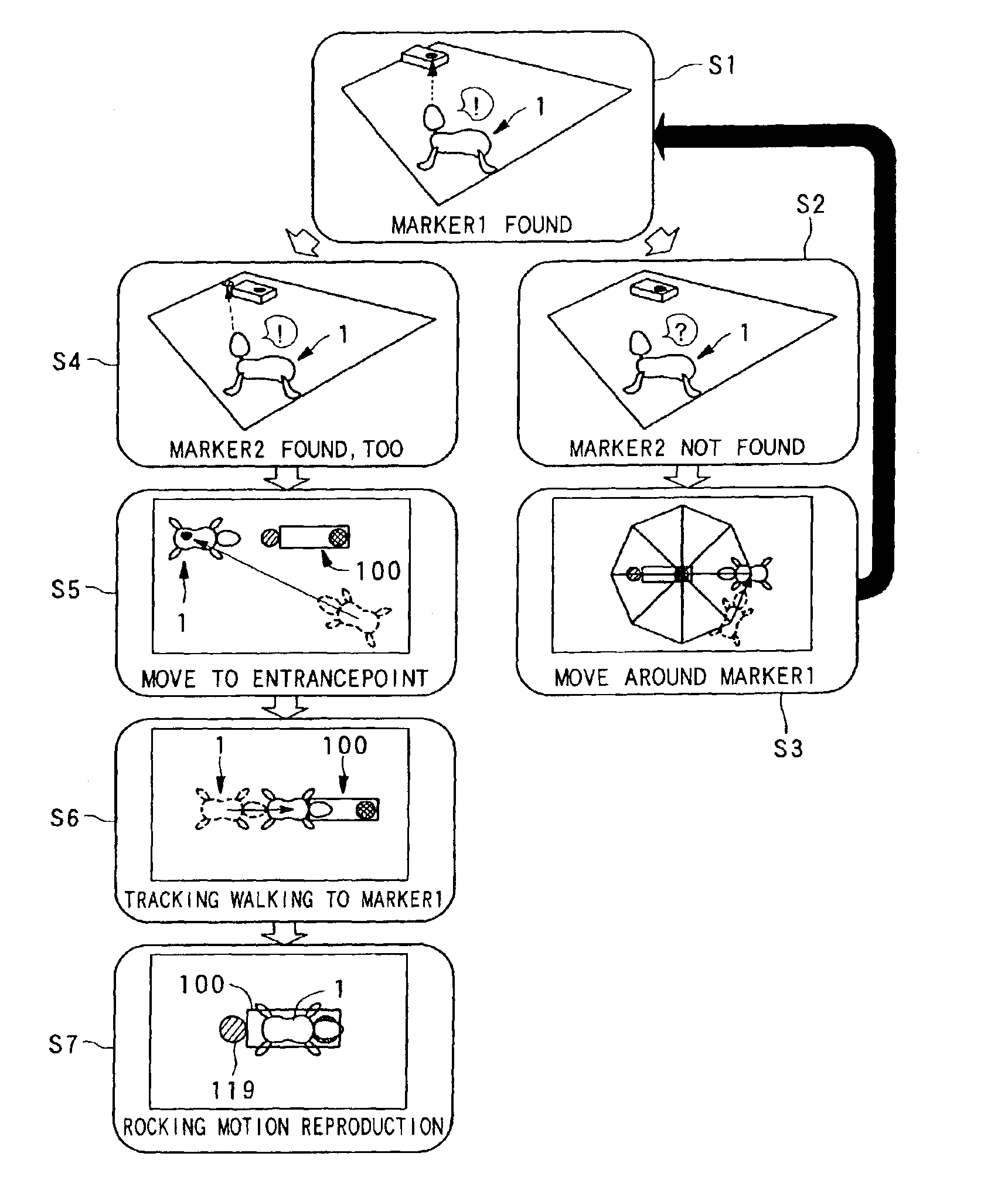
[0039]The electrical charging system according to the present invention is made up by a robot apparatus, having a built-in power supply and which is able to act autonomously responsive to its inner state, and an electrical charger for electrically charging a power supply. In this electrical charging system, the robot apparatus performs autonomous movements towards the electrical charger to start the electrical charging automatically. The robot apparatus is able to recognize the position of the electrical charger because the electrical charger is provided with a marker. The robot apparatus memorizes the position of this marker and finds the direction and the distance to the electrical charger from the photographed image of the marker and the pre-stored marker position.

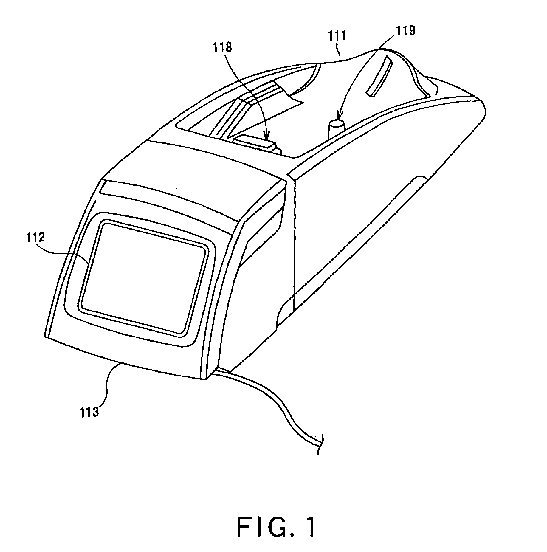
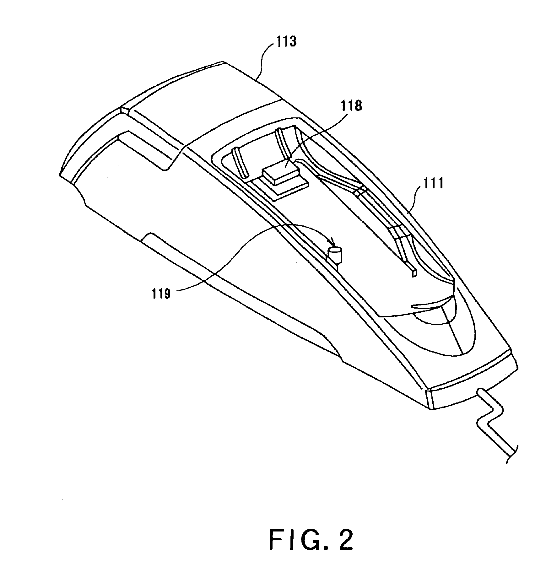
[0040]In the present embodiment, the structure of the electrical charger 100 is explained first and subsequently the robot apparatus is explained in detail. Referring to FIGS. 1 to 3, an illustrative structure of the el...


PUM


Abstract

A robot apparatus 1 is to be electrically charged autonomously. An electrical charging device 100 is provided with two markers, namely a main marker 118 and a sub-marker 119, and the heights of the markers are pre-stored in the robot apparatus. When the robot apparatus 1 is to find the direction and the distance to the electrical charging device 100, a CCD camera 20 finds the direction vector of the marker from the photographed image. This direction vector is transformed into a position vector of a camera coordinate system {c} and further into a position vector of the robot coordinate system {b}. The coordinate in the height-wise direction in the robot coordinate system {b} is compared to the pre-stored height to find the distance between the markers and the robot apparatus and the direction of the robot apparatus.

Description

BACKGROUND OF THE INVENTION[0001]1. Field of the Invention[0002]This invention relates to an electrical charging system, an electrical charging controlling method, a robot apparatus, an electrical charging device, an electrical charging controlling program, and a recording medium. This application claims priority of Japanese Patent Application No. 2002-090026, filed on Mar. 27, 2002, the entirety of which is incorporated by reference herein.[0003]2. Description of Related Art[0004]Recently, development in practically useful robots, supporting the human life as a partner, that is supporting the human activities in various aspects of our everyday life, such as in living environment, is progressing. In distinction from the industrial robots, these practically useful robots are endowed with the ability to learn for themselves the method for adaptation to human beings with variable personalities, or to variable environments, in the variegated aspects of our everyday life. For example, pe...

Claims


Application Information

Patent Timeline
IPC IPC(8): B25J19/00B25J19/02H02J7/00B25J5/00A63H11/00B25J13/08G05D1/02
CPCB25J19/005B25J19/023G05D1/0225G05D1/0246H02J7/00G05D2201/0214G05D1/0234
Inventor TSURUMI, SHINGO
Owner SONY CORP
Why Eureka
Try Eureka