Head-mounted displayed apparatus

Inactive Publication Date: 2005-07-05
CANON KK
View PDF12 Cites 21 Cited by
  • Summary
  • Abstract
  • Description
  • Claims
  • Application Information

AI Technical Summary

Benefits of technology

[0018]The invention is directed to the solution of the problems of the prior art described in the foregoing. It is, therefore, an object of the invention to provide a

Problems solved by technology

However, the above conventional head-mounted display apparatuses have problems, as described below, and the solution of the problems has been desired.
This adjusting mechanism increases the weight of the apparatus to degrade the light feeling of mounting.
Further, the partly-cutaway head-encompassing shape of the frame causes the size of the apparatus to increase.
However, it tends to eventually become impossible to obtain a necessary elastic force by adjustment.
In a case where a metal material is used as the elastic material, when the pressing holding member is spread for mounting the apparatus on the head, lack of design consideration as to properties and sectional shape of the material tends to incur a permanent set of fatigue with its internal stress coming to exceed the limit of elasticity.
The use of a metal material thus also necessitates the adjustment of the elastic force, which might eventually become impossible.
The display part is relatively heavy and requires use o

Method used


Image

  • Head-mounted displayed apparatus
  • Head-mounted displayed apparatus
  • Head-mounted displayed apparatus

Examples


Example

[0026]Hereinafter, a preferred embodiment of the invention will be described in detail with reference to the drawings.

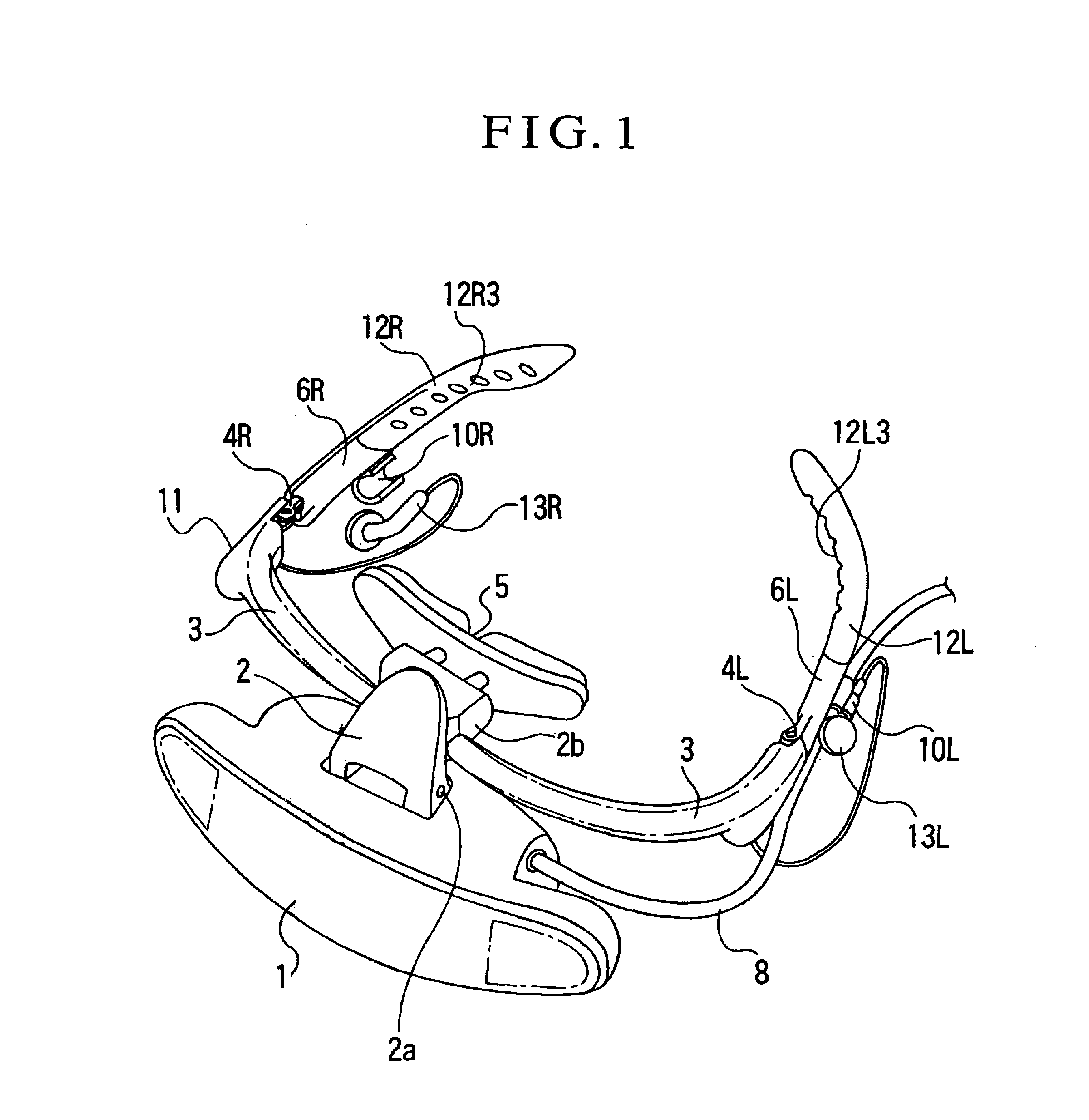
[0027]FIG. 1 is a perspective view showing the appearance of a head-mounted display apparatus according to the embodiment of the invention.

[0028]Referring to FIG. 1, the head-mounted display apparatus has a display part body 1 mounted on a front frame 3 through a holding member 2. Hinge parts 4L and 4R are mounted on the two end parts of the front frame 3. Side frames 6L and 6R are connected to the front frame 3 through the hinge parts 4L and 4R and are arranged to be foldable inward.

[0029]The display part body 1 contains a back light part, a liquid crystal panel, a display circuit and an optical member. The display part body 1 is pivotally supported by a rotary shaft 2a of the holding member 2 which is mounted on a middle part of the front frame 3 with screws. The display part body 1 is thus arranged to be swingable back and forth while retaining a certain amount of...


PUM


Abstract

A head-mounted display apparatus includes a front frame on which a display part is mounted and right and left side frames which are connected to the two end parts of the front frame by hinge parts in a foldable manner. An earphone-and-cable fixing part and an earphone fixing part are provided respectively on the lower sides of the right and left side frames. The earphone-and-cable fixing part has its end surface formed in a “3” like shape to allow a cable and the stem part of an earphone to be lightly inserted there. The earphone fixing part has its end surface formed in a “C” like shape to allow an earphone to be lightly inserted there. Elastic members provided at the right and left side frames are arranged to have their fore ends not touching right and left observation windows provided in the body of the display part in a state obtained with the side frames folded on the inner side of the front frame.

Description

BACKGROUND OF THE INVENTION[0001]1. Field of the Invention[0002]The present invention relates to a head-mounted display apparatus arranged to be mountable on the head of a user to enable the user to observe a video image.[0003]2. Description of Related Art[0004]Visual display apparatuses called the head-mounted display apparatus arranged to enable the user to see a video image, or an image from a personal computer, on the image plane of a display device mounted on the head of the user have been disclosed, for example, in Japanese Laid-Open Patent Applications No. HEI 7-84210, No. HEI 7-181422, No. HEI 7-333547, etc.[0005]With a head-mounted display apparatus mounted on the head of the user, the user can satisfactorily enjoy viewing video images or the like at any place without disturbing surroundings. The head-mounted display apparatus, therefore, must be easy to mount, light in weight, readily mountable and demountable and excel in portability. The known head-mounted display appara...

Claims


Application Information

Patent Timeline
IPC IPC(8): G02B27/02G09G5/00H04N5/64
CPCG02B27/0176
Inventor CHIGIRA, TATSUO
Owner CANON KK
Why Eureka
Try Eureka