Cell gap adjusting device, pressurizing seal device and liquid crystal display device manufacturing method

a technology of cell gap and pressurizing seal, which is applied in the direction of instruments, non-linear optics, optics, etc., can solve the problems of requiring a long time for the cell gap to reach a target value, and the inability to exert a desired pressure on both outer surfaces of the substrate, so as to achieve the effect of more accurate cell gap adjustmen

Inactive Publication Date: 2005-07-05
SEIKO EPSON CORP
View PDF21 Cites 29 Cited by
  • Summary
  • Abstract
  • Description
  • Claims
  • Application Information

AI Technical Summary

Benefits of technology

[0014]According to the cell gap adjusting device, one pair of substrate plates of a liquid crystal cell at both outer surfaces can be pressed by a pressure of a fluid introduced in the enclosed space. Accordingly, the cell gap can be correctly adjusted as compared to the conventional method that places the pressurizing members in direct contact with both outer surfaces of one pair of substrate plates to press both outer surfaces of the one pair of substrate plates.
[0033]This structure makes it possible to adjust the pressure to be exerted to both outer surfaces of the substrate plates of the liquid crystal cell in accordance with a current situation of the cell gap in the liquid crystal cell to be worked. Accordingly, the cell gap can be adjusted more accurately.

Problems solved by technology

Also, as in the foregoing, in the case of the conventional pressurizing method that pressurizing is made by alternately stacking liquid crystal cells and interposing papers, it is impossible to exert a desired pressure onto both outer surfaces of the substrate plates of the liquid crystal cell in a duration of from starting pressurizing to a full contraction of the interposing papers, correspondingly requiring a long time for the cell gap to reach a target value.

Method used


Image

  • Cell gap adjusting device, pressurizing seal device and liquid crystal display device manufacturing method
  • Cell gap adjusting device, pressurizing seal device and liquid crystal display device manufacturing method
  • Cell gap adjusting device, pressurizing seal device and liquid crystal display device manufacturing method

Examples


Embodiment Construction

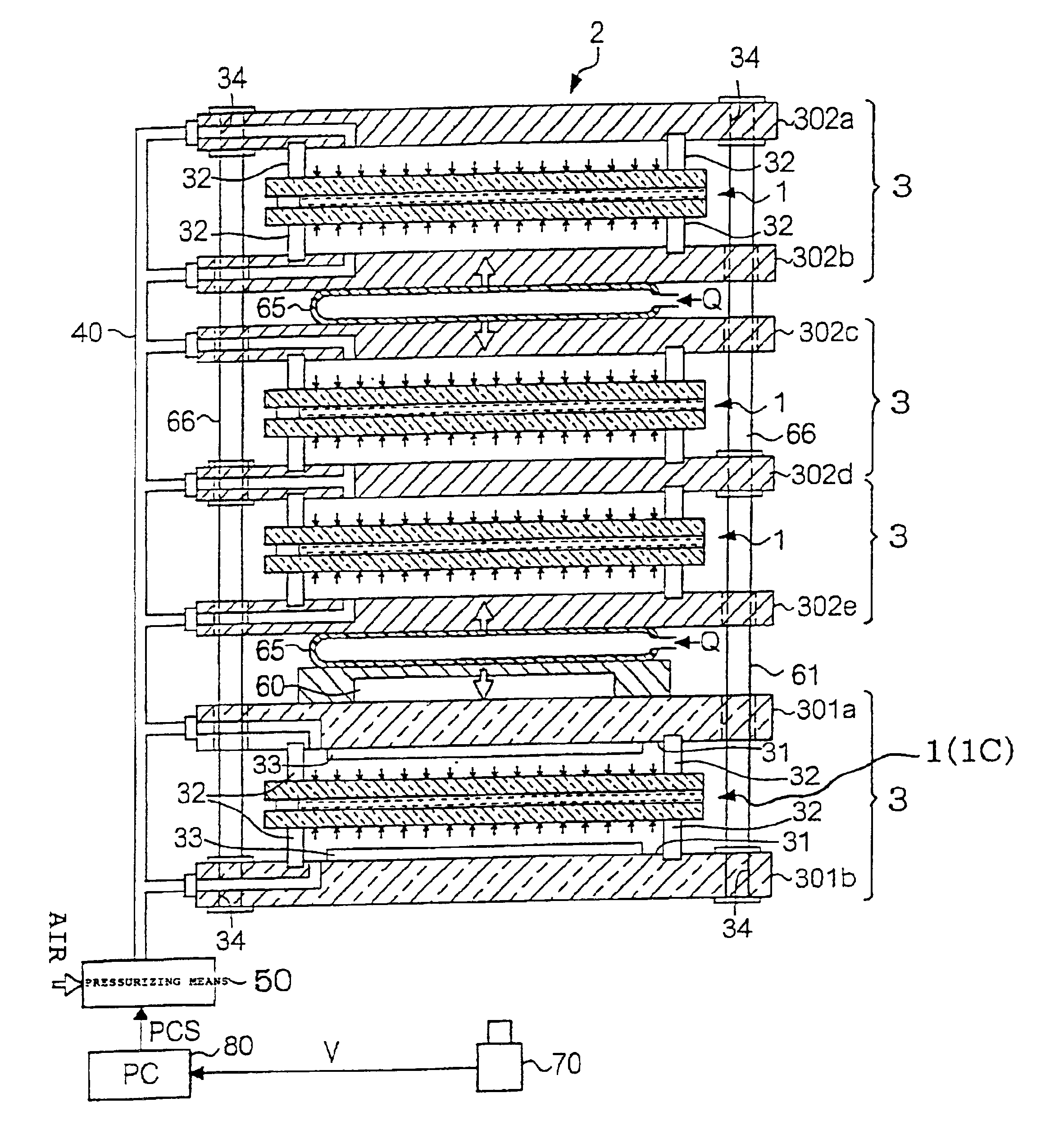
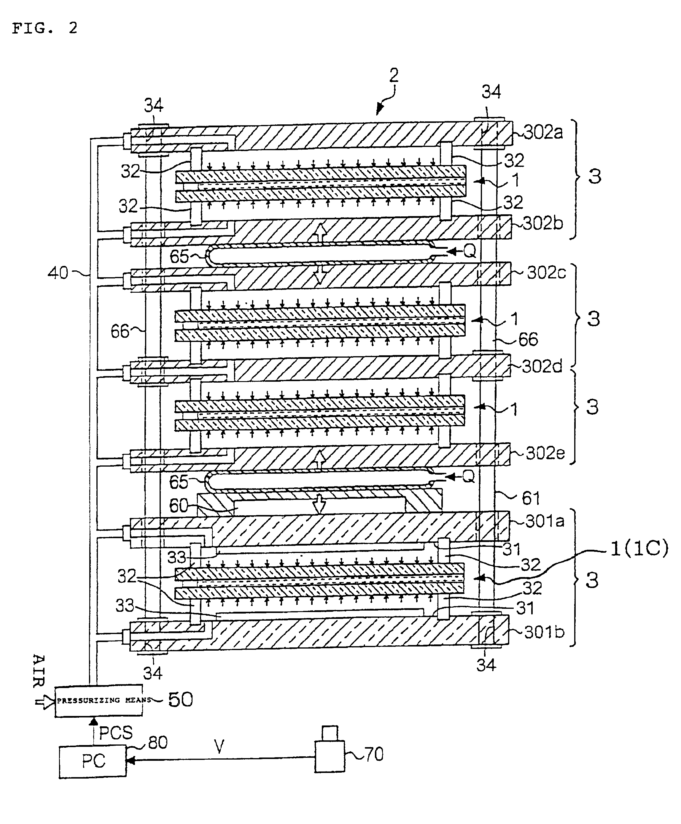
[0048]Hereunder, embodiments of the present invention will be explained with reference to the drawings. The embodiments represent one form of the invention and are not limitative of the invention and can be arbitrarily modified within the range of the invention.

[0049]A; Embodiment Structure

[0050](1) Liquid Crystal Cell (Group) Structure

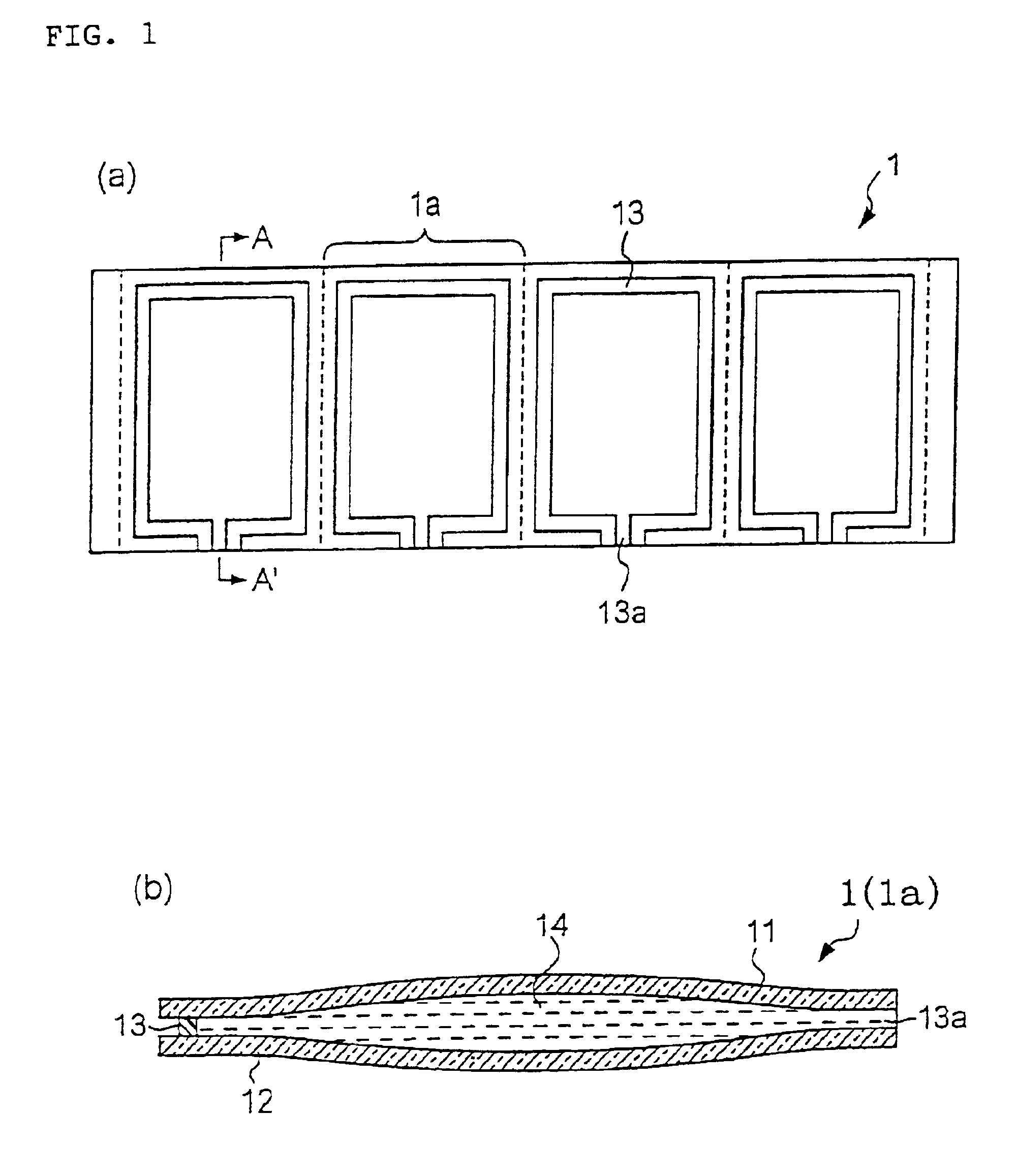
[0051]First, prior to explaining a structure of a cell gap adjusting device of the present embodiment, explanation is made on the structure of liquid crystal cells (liquid crystal cell group) to be worked by the device.

[0052]FIG. 1(a) is a plan view showing one example of a structure of the liquid crystal cell group 1, and FIG. 1(b) is a sectional view as viewed on line A-A′ in FIG. 1(a). As shown in the figures, the present embodiment explains a case that to be worked is a liquid crystal cell group 1 in a structure arrayed with four liquid crystal cells 1a. That is, first, as shown in FIGS. 1(a) and (b), a pair of substrate plates 11, 12 mutually opp...


PUM

PropertyMeasurementUnit
distanceaaaaaaaaaa
thicknessaaaaaaaaaa
pressureaaaaaaaaaa

Abstract

A cell gap adjusting device 2 for adjusting a thickness between a pair of substrate plates (cell gap) in a liquid crystal cell 1 having a liquid crystal filled between the pair of substrate plates bonded together through a seal member having a frame form and an opening in a predetermined point of a frame wall thereof, the cell gap adjusting device characterized by comprising: a supporting part 3 having one or more pairs of supporting jigs 30 (301a, 301b, 302a-302e) for clamping to support one or more of the liquid crystal cells 1 and closing seals 32 in a frame form arranged between the liquid crystal cell 1 and the supporting jigs 30 (301a, 301b, 302a-302e) to form an enclosed space by both outer surfaces of the pair of substrate plates of the liquid crystal cell 1, opposed surfaces of the one pair of support jigs 30 (301a, 301b, 302a-302e) to the liquid crystal cell 1 and an inner surface thereof (of the closing seal); and a pressurizing part 50 for simultaneously pressurizing both outer surfaces of the one pair of substrate plates of the liquid crystal cell 1 by the pressure of a fluid introduced in the enclosed space.

Description

BACKGROUND OF THE INVENTION[0001]1. Technical Field to Which the Invention Belongs[0002]The present invention relates to a cell gap adjusting device, pressurizing seal device and liquid crystal display device manufacturing method for adjusting a thickness between a pair of substrate plates (hereinafter, referred to as “cell gap”) in a liquid crystal cell.[0003]2. Prior Art[0004]It is a general practice to manufacture a conventionally widespread liquid crystal device by bonding together an opposing pair of substrate plates through a seal member having a frame form and an opening at a predetermined point in a frame wall thereof into a cell, filling a liquid crystal into the cell through the opening in the seal member, and sealing the opening with a seal material. Herein, the method for filling a liquid crystal into the cell broadly uses a so-called vacuum filling method. That is, a chamber having cells arranged is evacuated into a vacuum state, so that, if the atmospheric pressure is ...

Claims


Application Information

Patent Timeline
Patent Type & Authority Patents(United States)
IPC IPC(8): G02F1/13G02F1/1333G02F1/1341G02F1/1339G02F1/13357
CPCG02F1/1333G02F1/1341G02F1/1339
Inventor MASUDA, KENJIKUROIWA, MASAHIRO
Owner SEIKO EPSON CORP
Why Eureka
Try Eureka