Mirror device, optical switch, electronic instrument and mirror device driving method

a technology of mirror device and driving method, which is applied in the direction of mountings, optics, instruments, etc., can solve the problems of not being able to suitably solve the problem and producing a large displacement of a mirror with so as to achieve a smaller driving force and a larger driving effect of the mirror

Inactive Publication Date: 2005-07-05
SEIKO EPSON CORP
View PDF9 Cites 73 Cited by
  • Summary
  • Abstract
  • Description
  • Claims
  • Application Information

AI Technical Summary

Benefits of technology

[0024]According to a mirror device or the like of the present invention, when a mirror is driven by a distance-dependent driving force (for example, a coulomb force or an electromagnetic force, or the like), the distance-dependent driving force is generated towards the mirror side from a part of the mirror substrate positioned away from the mirror and a part of the support substrate positioned opposite that part of the mirror substrate, so that gaps between parts of the mirror substrate and parts of the support substrate positioned opposite to that parts of the mirror substrate gradually narrow, whereby it is possible to narrow a gap between the mirror and a part of the support substrate positioned opposite to the mirror.
[0047]According to this feature, it is possible in a mirror device or the like, to produce a large driving effect to a mirror by using a coulomb force (electrostatic force), even when driving with a low voltage. By using an electrostatic driving method in a mirror device or the like, it is possible to reduce heat generation and power consumption required for driving the mirror.

Problems solved by technology

One problem when driving a mirror device is how to produce a large displacement for a mirror with a smaller driving force.
In this way, it is not possible to suitably solve the problem of producing a larger driving effect to a mirror with a smaller driving force.

Method used


Image

  • Mirror device, optical switch, electronic instrument and mirror device driving method
  • Mirror device, optical switch, electronic instrument and mirror device driving method
  • Mirror device, optical switch, electronic instrument and mirror device driving method

Examples


embodiment

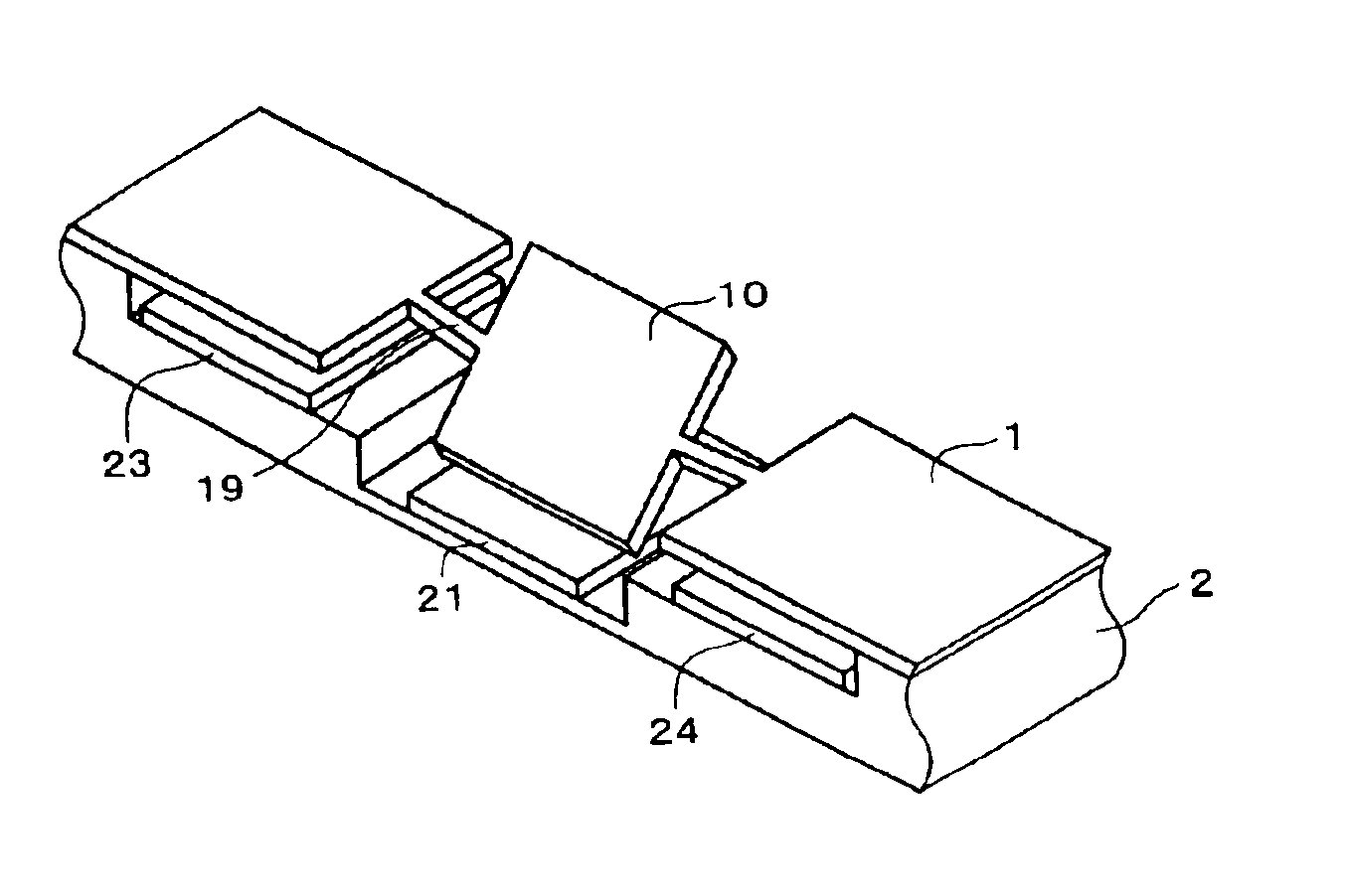
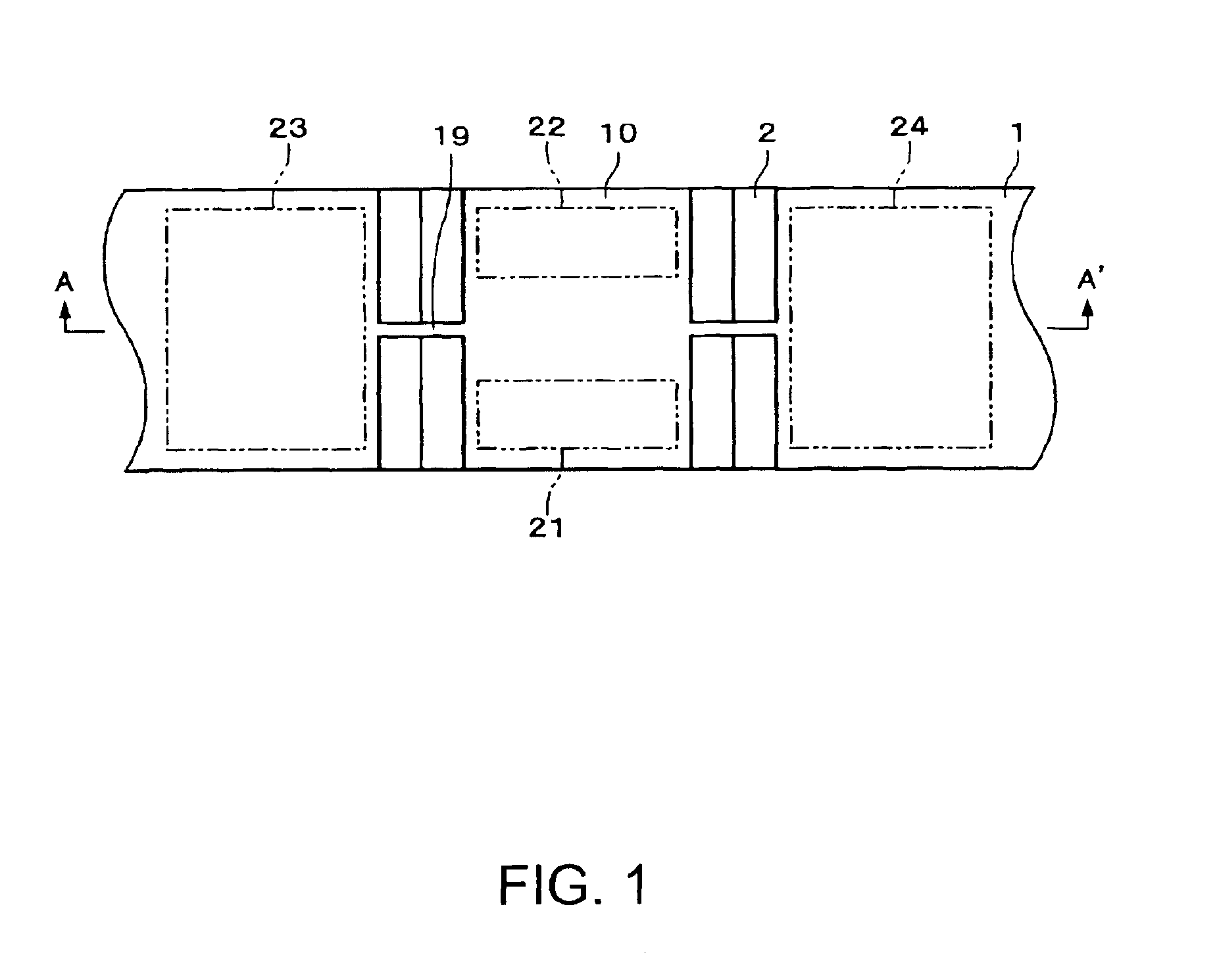
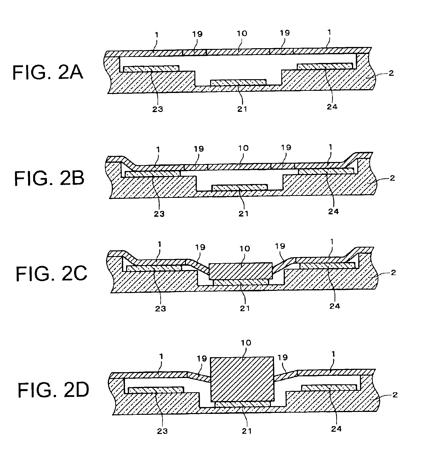
[0056]FIG. 1 is a plan view showing a mirror device according to one embodiment. FIGS. 2A to 2D are cross-sectional views of the mirror device according to this embodiment, with FIG. 2A being a cross-sectional view of the mirror device in an initial state, FIG. 2B being a cross-sectional view of the mirror device in a state where a part of a silicon substrate 1 other than a mirror 10 have been attracted towards a glass substrate 2, FIG. 2C being a cross-sectional view of the mirror device in a state where the mirror 10 has been attracted towards the silicon substrate 1, and FIG. 2D being a cross-sectional view of the mirror device in a state where the part of the silicon substrate 1 other than the mirror 10 have been separated from the glass substrate 2. FIGS. 3A to 3D are perspective views of the mirror device according to this embodiment, with FIG. 3A being a perspective view of the mirror device in the initial state, FIG. 3B being a perspective view of the mirror device in the st...


PUM


Abstract

To provide a mirror device, an optical switch, an electronic instrument, and a mirror device driving method in which a large driving displacement can be produced for a mirror with a smaller driving force, a silicon substrate includes: at least one first mirror-side operating region integrally formed with the mirror and provided at a different position from the mirror; and at least one second mirror-side operating region provided at an end portion of the mirror, and a glass substrate includes: an opposite-side operating section, a coulomb force acting between the first mirror-side operating region and the opposite-side operating section; and another opposite-side operating section, the coulomb force acting between the second mirror-side operating region and the other opposite-side operating section. The glass substrate is formed so that a gap between the first mirror-side operating region and the opposite-side operating section is narrower than a gap between the second mirror-side operating region and the opposite-side operating section.

Description

[0001]Japanese Patent Application No. 2002-281084 filed on Sep. 26, 2002 is hereby incorporated by reference in its entirety.BACKGROUND OF THE INVENTION[0002]The present invention relates to a mirror device, an optical switch, an electronic instrument, and a mirror device driving method.[0003]One problem when driving a mirror device is how to produce a large displacement for a mirror with a smaller driving force.[0004]In order to solve this problem, Japanese Patent Application Laid-Open No. 2001-311900 proposes an optical scanning apparatus that is equipped with opposing electrodes that have inclined surfaces on their lower surfaces in a mirror driving direction, with grooves being provided in the incline direction of these inclined surfaces.[0005]When the driving force for driving the mirror device is provided electrostatically by a coulomb force, for example, the driving force is dependent on distance in that the driving force increases as the distance between the electrodes decre...

Claims


Application Information

Patent Timeline
Patent Type & Authority Patents(United States)
IPC IPC(8): G02B26/08
CPCG02B26/0841G02B26/085Y10S359/90
Inventor KUROSAWA, RYUICHI
Owner SEIKO EPSON CORP
Why Eureka
Try Eureka