Method and system for VLAN aggregation

a technology of virtual local area networks and aggregation, applied in the field of virtual local area network topologies and internetwork communication technologies, can solve the problems of inefficient and unnecessary use of the limited number of unique networks, the increase of the global routing table needed to properly route data packets, and the overhead of ip address space of subnets. large,

Inactive Publication Date: 2005-07-05
ARISTA NETWORKS
View PDF93 Cites 132 Cited by
  • Summary
  • Abstract
  • Description
  • Claims
  • Application Information

AI Technical Summary

Benefits of technology

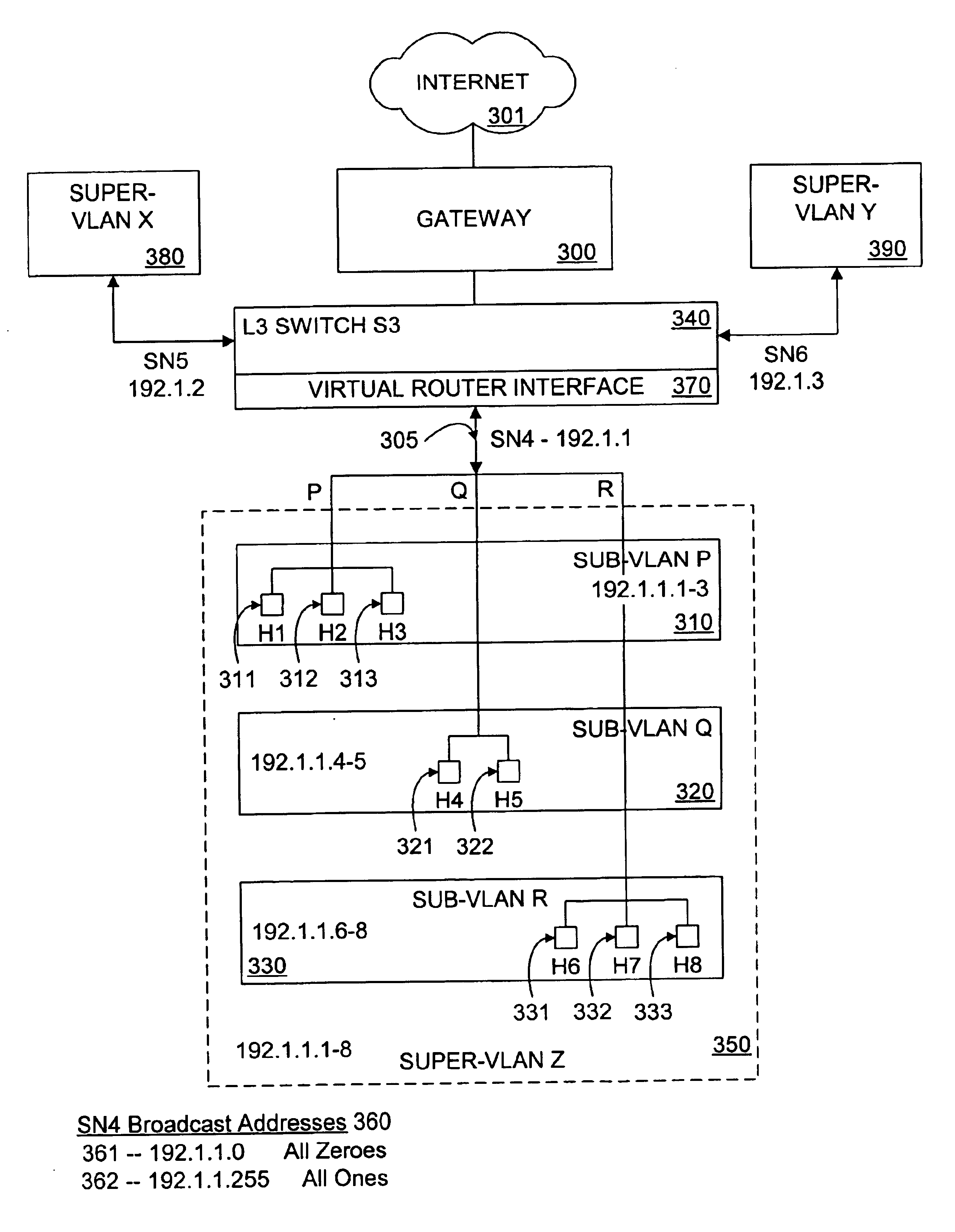
[0024]According to one aspect of the invention, a method and system is provided in which an aggregated VLAN network architecture is used in forwarding data packets by a LAN switch connecting multiple VLANs. Instead of assigning each subscriber's VLAN to one subnet, the method and system of the present invention assigns each subscriber to a “sub-VLAN” that shares a subnet with other subscribers' sub-VLANs. All of the sub-VLANs sharing the same subnet are hierarchically organized into a single “super-VLAN.” The super-VLAN is uniquely associated with that same subnet, and each sub-VLAN of the super-VLAN shares in the host address space supported by that subnet. As a result, the sub-VLANs can also 1) share the same virtual router interface (i.e. the routing configuration from the super-VLAN subnet), 2) configure the same default router, and 3) share the same subnet mask. By using VLAN aggregation architecture, the switches embodied by the present invention not only enable IP address conservation and routing efficiency, but are capable of separating subnet-like traffic between individual subscribers of unpredictable size.

Problems solved by technology

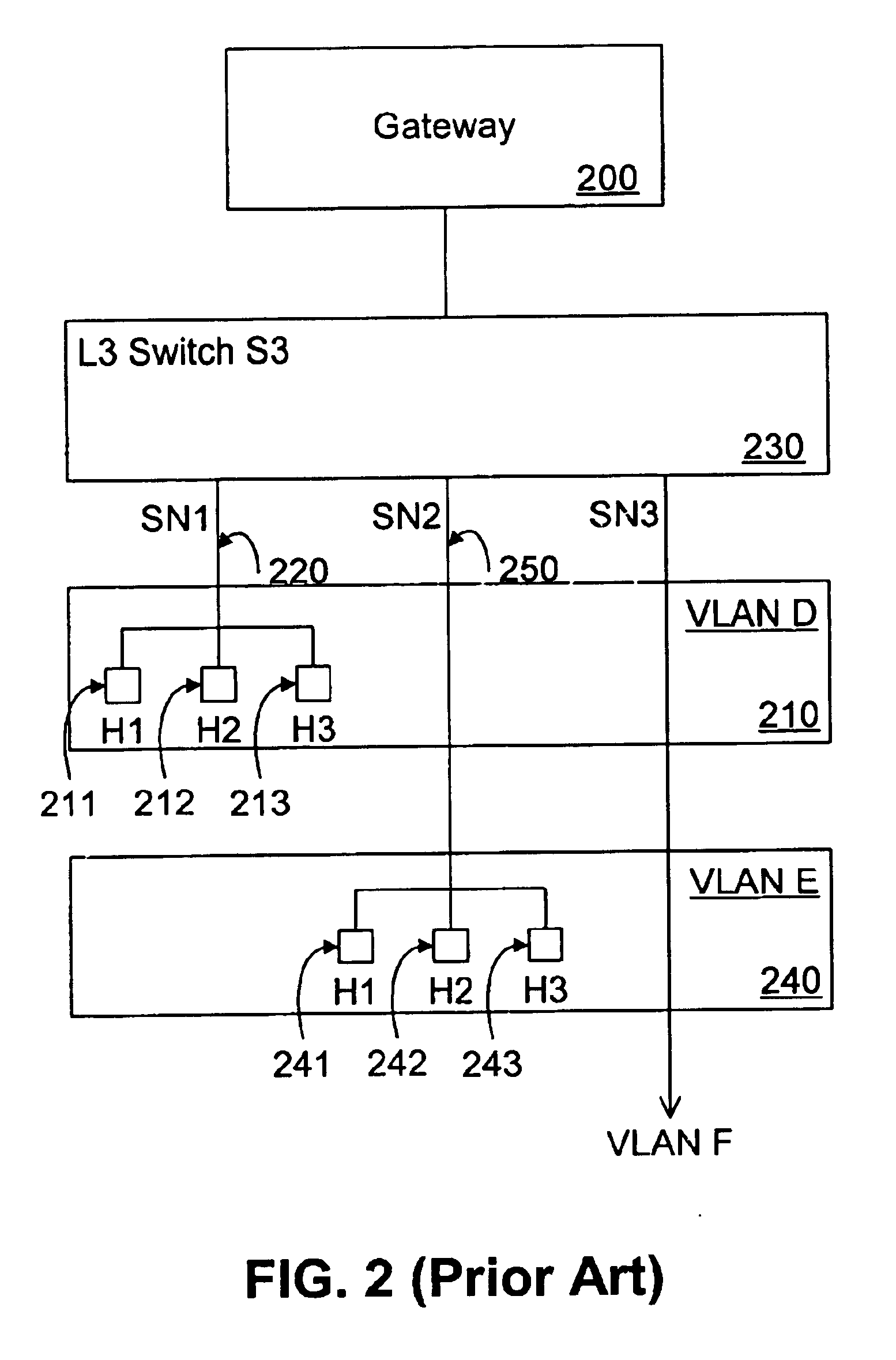
Without subnets, an ISP could get multiple connections to the Internet, one for each of its logically separate networks, but this would result in an inefficient and unnecessary use of the limited number of unique network numbers, as well as an unnecessary increase in the size of the global routing tables needed to properly route data packets from one network to another.
However, there are a number of drawbacks to assigning each subscriber their own VLAN based on a unique subnet address.
One drawback is that implementations of a subnet addressing scheme must set aside certain special purpose IP addresses that cannot be used for host IP addresses.
As a result of having to set aside these four types of special purpose and broadcast IP addresses, the IP address space overhead of subnets can become quite large, particularly when dividing a given IP network address space up into several smaller subnets, as is often the case in an ISP environment.
When multiplied by hundreds and thousands of subscriber subnets, this represents a significant waste of the available IP address space.
Another drawback to assigning each subscriber their own unique subnet, is the requirement of storing another 32-bit number, called a subnet mask, to support the interpretation of the IP addresses for each different subnet.
Therefore, the use of subnets results in an unavoidable amount of subnet mask storage and processing overhead that must be incurred when forwarding and routing data packets.
Yet another drawback to assigning each subscriber their own individual subnet is the constraints on the number and size of subnets imposed by the subnet addressing scheme itself.
Since ISPs often service subscribers of varying and unpredictable size, assigning each subscriber an individual subnet can result in extremely inefficient allocation of the available host address space.
As the demand for Internet access has grown, the necessity of conserving IP address space and reducing routing overhead has become more critical.

Method used


Image

  • Method and system for VLAN aggregation
  • Method and system for VLAN aggregation
  • Method and system for VLAN aggregation

Examples


Embodiment Construction

[0029]In the following description various aspects of the present invention, a VLAN aggregation method and system, will be described. Specific details will be set forth in order to provide a thorough understanding of the present invention. However, it will be apparent to those skilled in the art that the present invention may be practiced with only some or all of the described aspects of the present invention, and with or without some or all of the specific details. In some instances, well known architectures, steps, and techniques have not been shown to avoid unnecessarily obscuring the present invention. For example, specific details are not provided as to whether the method and system is implemented in a router, server or gateway, as a software routine, hardware circuit, firmware, or a combination thereof.

[0030]Various operations will be described as multiple discrete steps performed in turn in a manner that is most helpful in understanding the present invention. However, the ord...


PUM


Abstract

A method and system for an aggregated virtual local area network (VLAN) architecture in which several VLANs in a network share the same default router address and subnet mask, but remain isolated from one another's network traffic. Instead of the traditional method of assigning one subnet to a VLAN, each VLAN is assigned only a portion of a subnet's IP address space, and is further grouped into a super-VLAN uniquely associated with that subnet. Intra-VLAN traffic is forwarded only to host IP addresses assigned to that same VLAN according to a VLAN identifier carried in the data packet. Inter-VLAN traffic is processed by a virtual router interface which routes the data packet by applying the routing configuration for the subnet uniquely associated with the super-VLAN, according to a super-VLAN identifier carried in the data packet. The routing configuration used by the virtual router interface includes routing protocols, static routes, redundant router protocols and access-lists. Since each VLAN shares the same virtual router interlace, the traditional address overhead of a subnet is minimized, requiring only one default router and subnet mask, as well as only one pair of subnet broadcast addresses for all hosts on the subnet and the subnet itself. The aggregated VLAN architecture provides for the efficient use and management of a network's IP address space.

Description

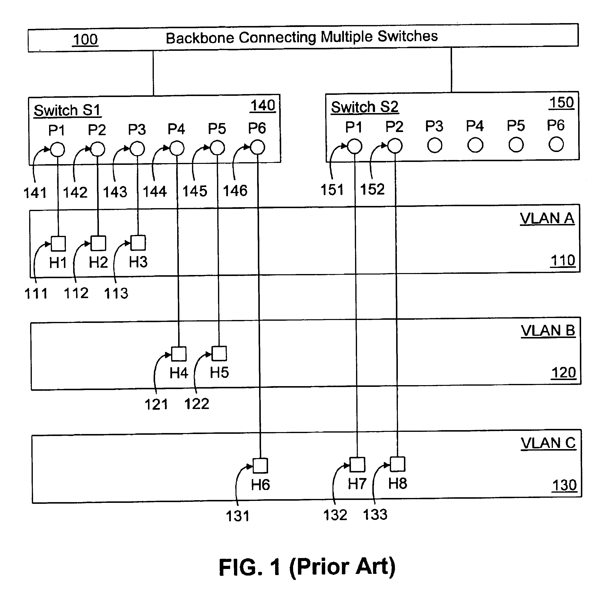
BACKGROUND OF THE INVENTION[0001]1. Field of the Invention[0002]The present invention relates to the field of virtual local area network (VLAN) topologies and internetwork communications technologies. In particular, the present invention relates to an aggregated VLAN network architecture used in forwarding data packets by a LAN switch connecting multiple VLANs.[0003]2. Background Information and Description of Related Art[0004]A VLAN is a logical grouping of networked host computers on some other basis than the physical network location (e.g. department, primary application). VLANs allow network managers to more easily manage dynamic networks where the identity and location of the network's users are constantly changing.[0005]VLANs can be implemented in a number of different ways, depending on the network strategy. A prior art traditional layer-2 VLAN is based on a logical grouping of the layer-2 switch ports to which the hosts connect. Alternative prior art layer-2 VLANs define VLA...

Claims


Application Information

Patent Timeline
Patent Type & Authority Patents(United States)
IPC IPC(8): H04L12/56H04L12/46H04L29/12
CPCH04L12/4641H04L29/12009H04L29/12783H04L29/12801H04L45/00H04L45/586H04L61/35H04L61/6004H04L61/00H04L2101/604
Inventor YIP, MICHAELMERCHANT, SHEHZAD T.YIN, KENNETH T.
Owner ARISTA NETWORKS
Why Eureka
Try Eureka