Signal modulation circuit and signal modulation method

a signal modulation circuit and signal technology, applied in the direction of pulse frequency/rate modulation, digital transmission, electric devices, etc., can solve the problems of increasing the disadvantageous volume and cost of the signal modulation system, using many voluminous and expensive filters,

Inactive Publication Date: 2005-07-05
KK TOSHIBA
View PDF19 Cites 27 Cited by
  • Summary
  • Abstract
  • Description
  • Claims
  • Application Information

AI Technical Summary

Problems solved by technology

It is necessary to use many voluminous and expensive filters to remove such out of band undesired component.
There is a problem of increasing disadvantageously volume and cost of signal modulation system.

Method used


Image

  • Signal modulation circuit and signal modulation method
  • Signal modulation circuit and signal modulation method
  • Signal modulation circuit and signal modulation method

Examples


Embodiment Construction

[0112]Now, an embodiment of signal modulation circuit of the present invention will be described referring to attached drawings.

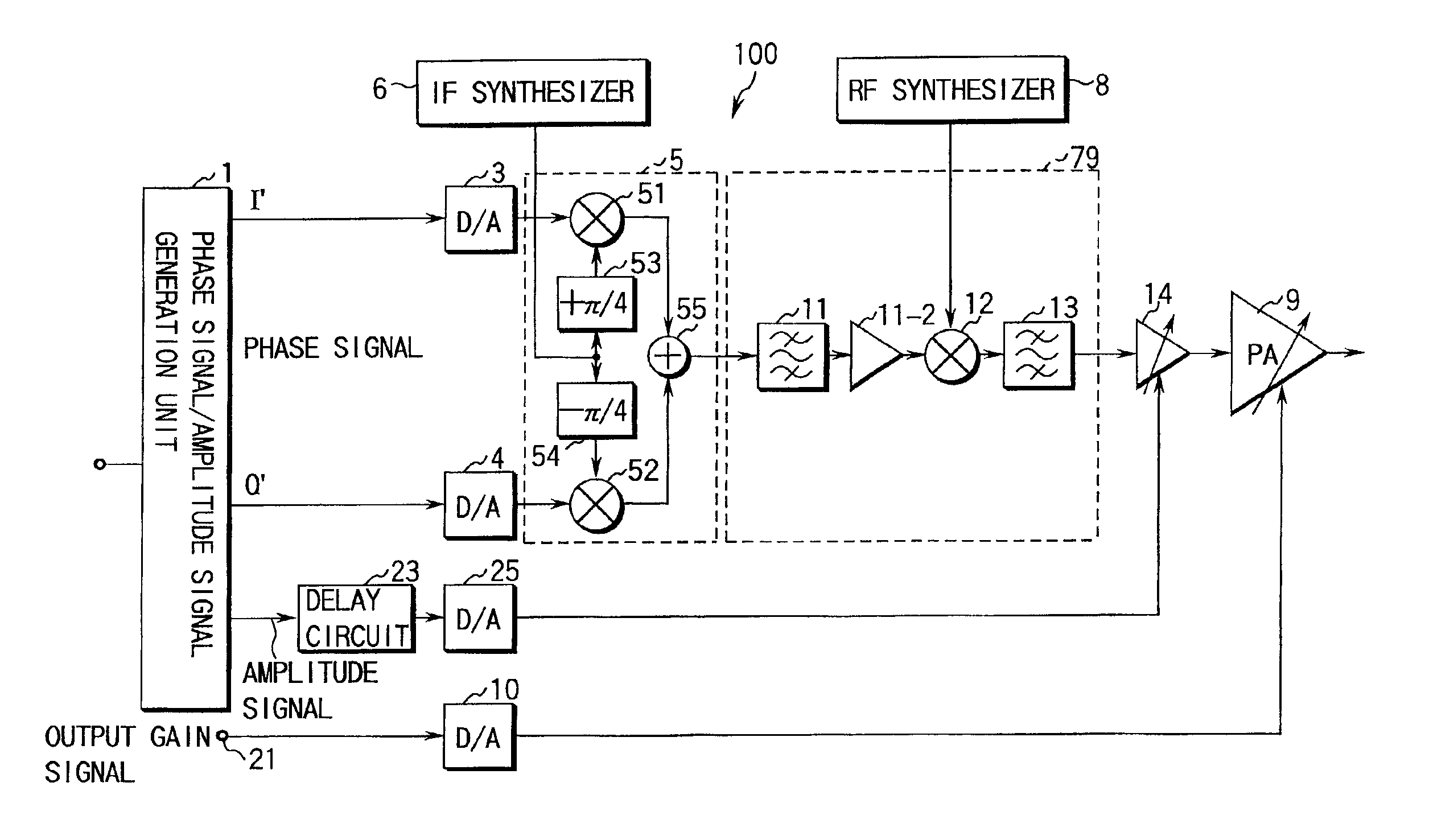
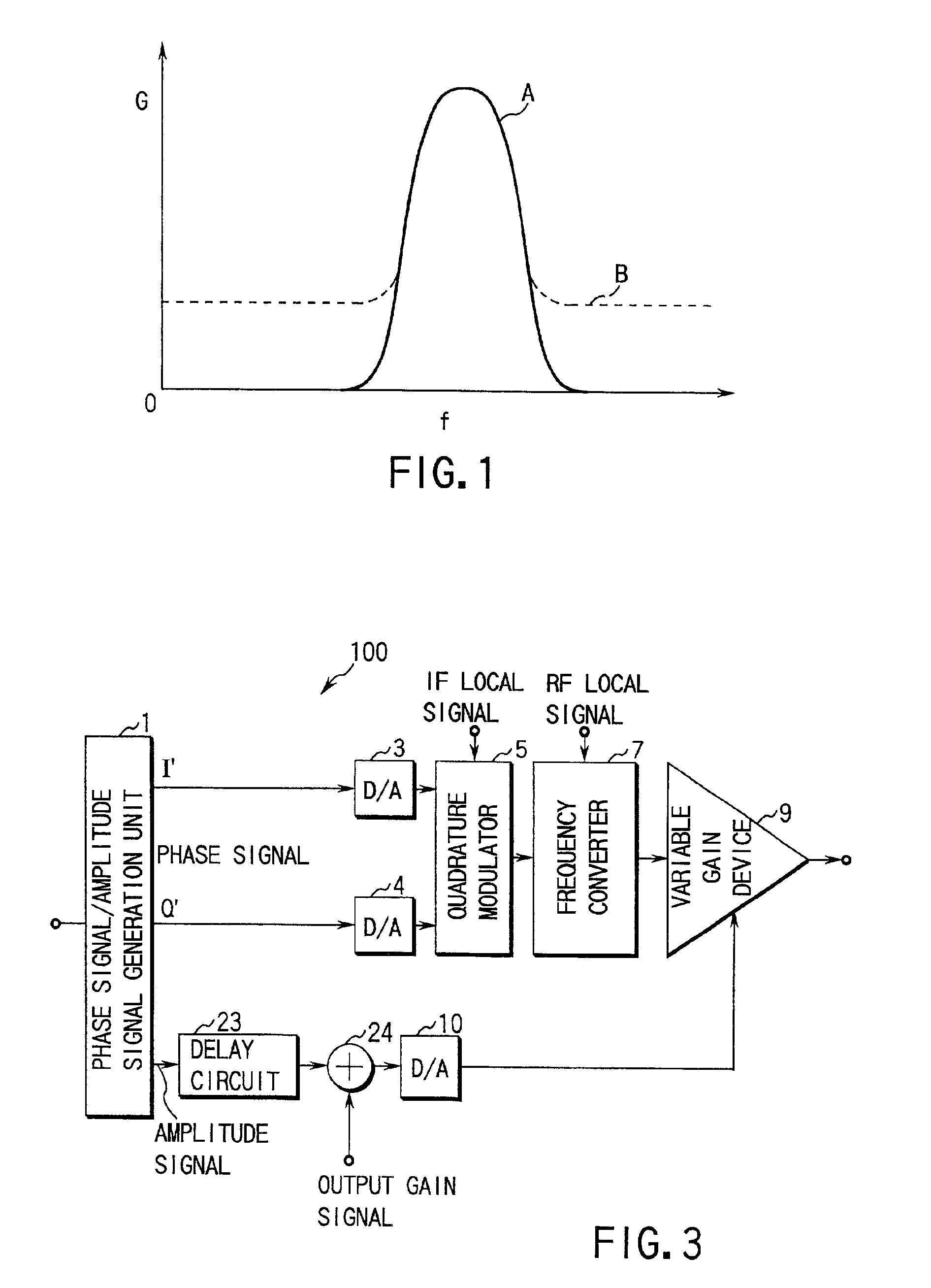
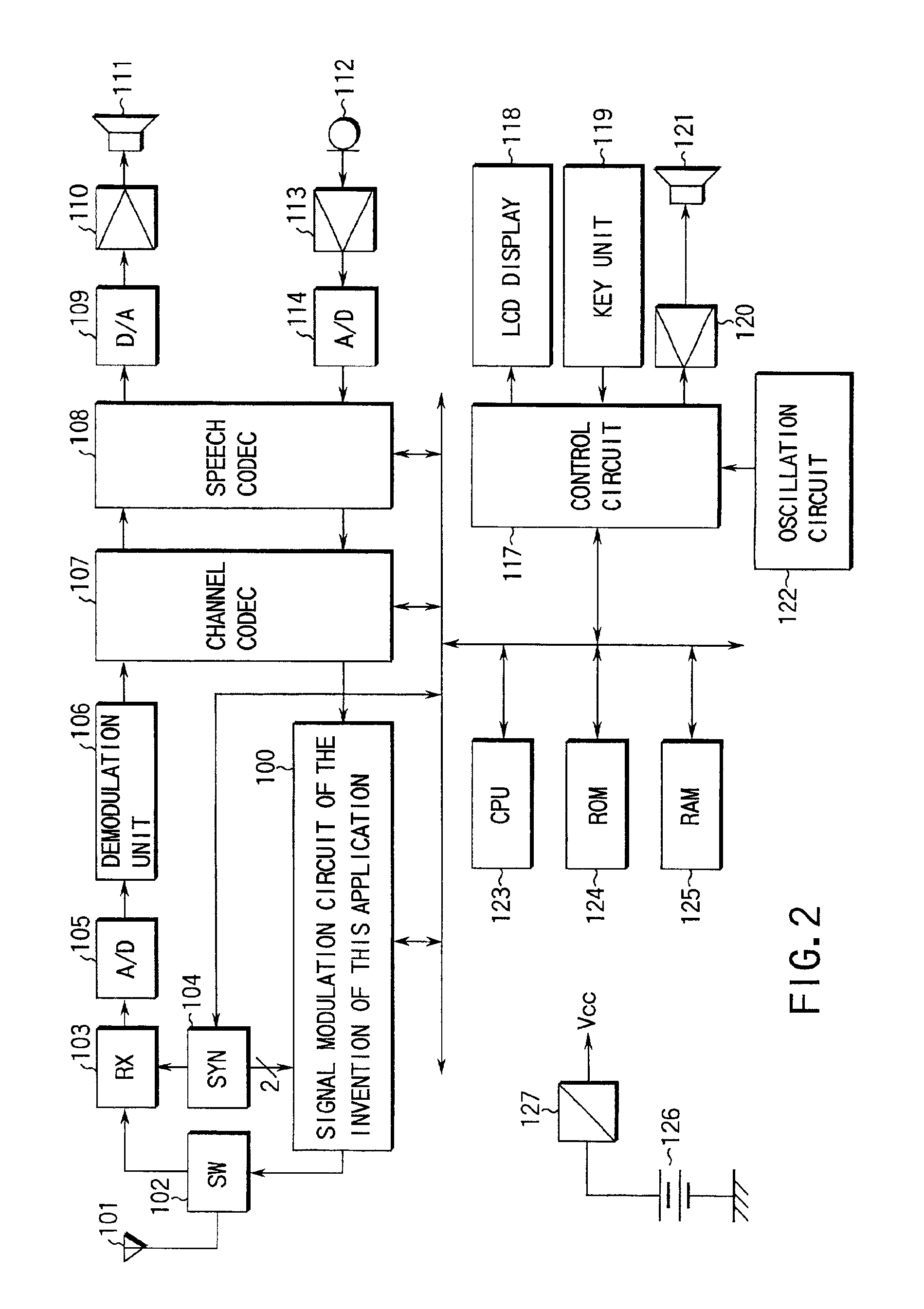
[0113]A concrete example of a signal modulation circuit and a signal modulation method according to an embodiment of the present invention will be described referring to FIG. 2 to FIG. 10. FIG. 2 is a block diagram showing the construction of essential parts of a cellular phone including a signal modulation circuit 100 according to this embodiment.

[0114]The cellular phone shown in FIG. 2 comprises an antenna 101, an antenna switch 102, a receiving circuit (RX) 103, a synthesizer circuit (SYN) 104, an analog / digital (A / D) converter 105, a demodulation unit 106, a channel codec 107, a speech codec 108, a digital / analog (D / A) converter 109, a speaker amplifier 110, a speaker 111, a microphone 112, a microphone amplifier 113, an A / D converter 114, a control circuit 117, an LCD display 118, a key unit 119, an amplifier 120, a sounder 121, an oscillation circuit ...


PUM


Abstract

A phase signal is modulated in quadrature modulation by a quadrature modulator, and the frequency of this modulated phase signal is converted into carrier frequency by a frequency converter. An amplitude signal extracted from the modulating signal is delayed by a delay circuit, and an output gain signal designating the output average power gain is supplied to the output signal of the delay circuit. Synchronization of this frequency modulated phase signal and the amplitude signal delayed and added to the output gain signal allows to obtain an RF signal with little out of band undesired component even if the modulating signal contains amplitude variation. Therefore, the RF signal with little out of band undesired component is output even if the modulating signal contains amplitude variation.

Description

CROSS-REFERENCE TO RELATED APPLICATIONS[0001]This is a Continuation Application of PCT Application No. PCT / JP00 / 02124, filed Mar. 31, 2000, which was not published under PCT Article 21(2) in English.[0002]This application is based upon and claims the benefit of priority from the prior Japanese Patent Application No. 11-091717, filed Mar. 31, 1999, the entire contents of which are incorporated herein by reference.BACKGROUND OF THE INVENTION[0003]1. Field of the Invention[0004]The present invention relates to a signal modulation circuit and a signal modulation method and, especially, a signal modulation circuit and a signal modulation method for modifying a signal based on a phase signal and an amplitude signal extracted from a modulating signal and, for example the signal modulation circuit and the signal modulation method for modifying a signal in the transmission unit of a cellular phone.[0005]2. Description of the Related Art[0006]Some of conventional signal modulation circuits an...

Claims


Application Information

Patent Timeline
Patent Type & Authority Patents(United States)
IPC IPC(8): H04L27/34H04L27/36H04N5/40
CPCH04L27/361
Inventor SHIMIZU, HIROAKI
Owner KK TOSHIBA
Why Eureka
Try Eureka