Air conditioning system

a technology of air conditioning system and air conditioner, which is applied in the field of air conditioning system, can solve the problems of contaminating room air, not controlling humidity, and users' unpleasant feelings

Inactive Publication Date: 2005-07-12
LG ELECTRONICS INC
View PDF10 Cites 27 Cited by
  • Summary
  • Abstract
  • Description
  • Claims
  • Application Information

AI Technical Summary

Benefits of technology

[0011]Accordingly, the present invention is directed to an air conditioning system that substantially obviates one or more of the problems due to limitations and disadvantages of the related art.
[0012]An object of the present invention is to provide an air conditioning system having functions of cooling / heating, ventilation, and dehumidification.

Problems solved by technology

However, the cooling / heating system, cooling or heating the room air and circulating through the room repeatedly, contaminates room air and can not control humidity.
When the room air is contaminated, and the humidity is not controlled, users feel unpleasant, and open a window for ventilation.
Moreover, the discharge of room air to an exterior in the ventilation causes a large amount of energy loss, to require a large power consumption for cooling or heating required for brining the room temperature to a preset room temperature.

Method used


Image

  • Air conditioning system
  • Air conditioning system
  • Air conditioning system

Examples


first embodiment

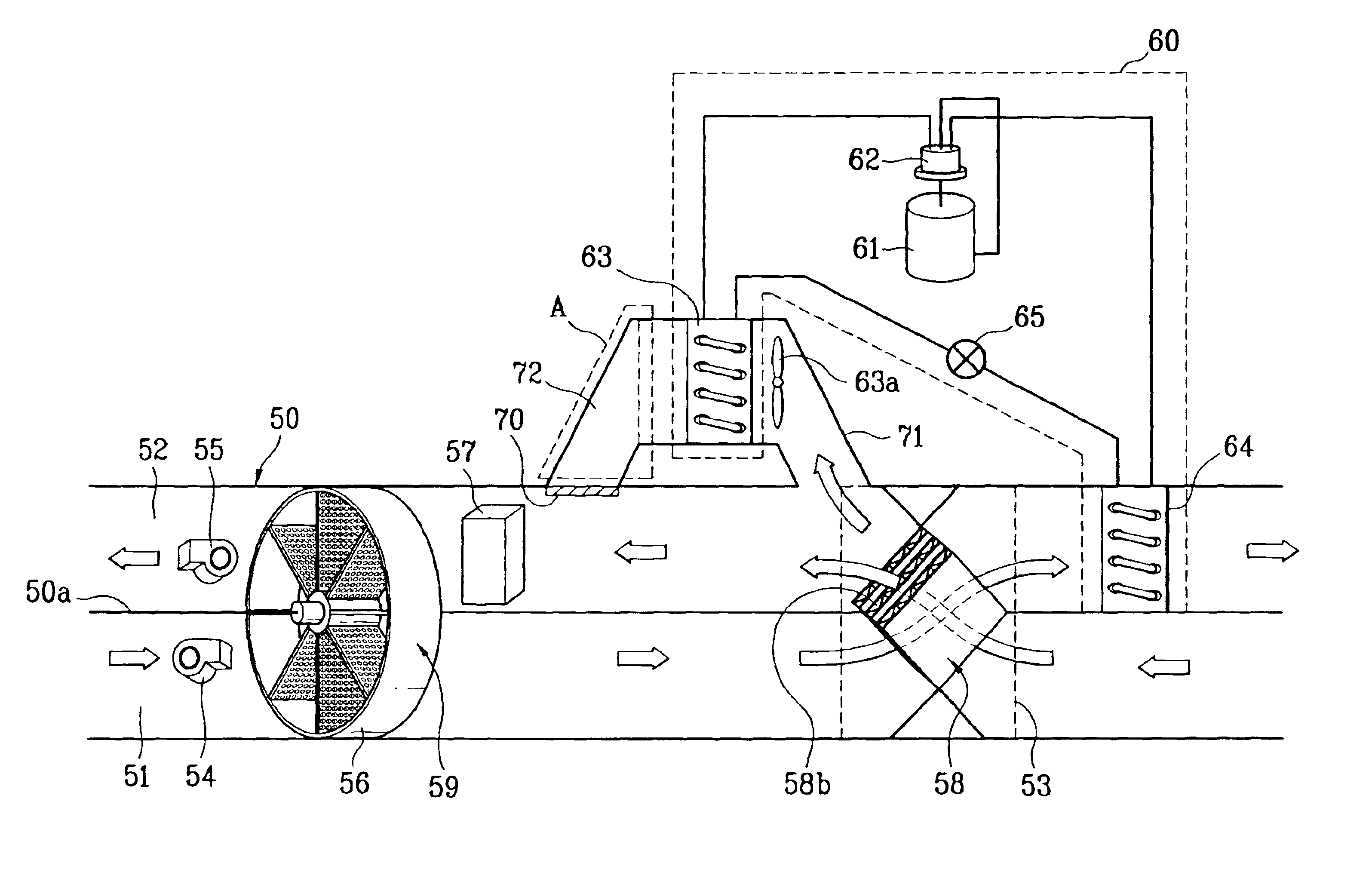
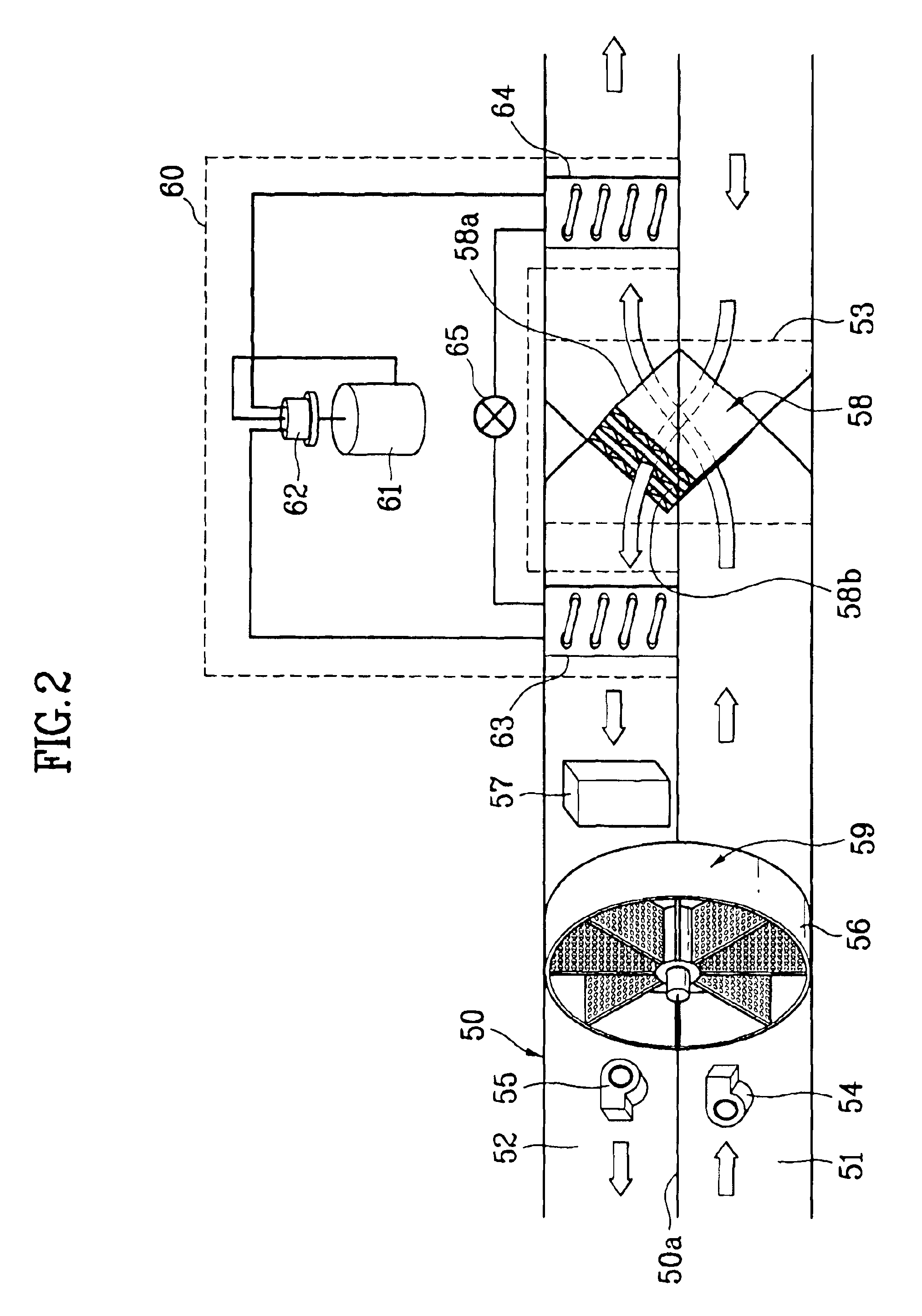
[0031]the present invention will be described, with reference to the attached drawings. FIG. 2 illustrates a diagram of an air conditioning system in accordance with a first preferred embodiment of the present invention, and FIG. 3 illustrates a perspective view of the desiccant wheel in the dehumidifier in FIG. 2.

[0032]Referring to FIG. 2, the air conditioner of the present invention includes a duct 50, a suction fan 54, a discharge fan 55, a regenerative heat exchanger 58, and a heat pump 60.

[0033]The duct 50 has a suction passage 51 and a discharge passage 52 split with a split plate 50a. The suction fan 54 is mounted in the suction passage 51 for drawing external air, and the discharge fan 55 is mounted in the discharge passage 52 for discharging room air.

[0034]In the meantime, there is a dehumidifier 59 in an opening at one side of the split plate 50a. The dehumidifier 59 has desiccant on an outside surface, and a rotatable desiccant wheel 56, so that the dehumidifier 59 absorb...

second embodiment

[0053]A second preferred embodiment of the present invention that is a modification of the first preferred embodiment will be described with reference to FIG. 5. The second embodiment air conditioning system includes a parallel passage 71 mounted in, and parallel to the discharge passage 52, further.

[0054]Referring to FIG. 5, the parallel passage 71 is mounted in, and parallel to the discharge passage 52 between the dehumidifier 59 and the regenerative heat exchanger 58. The first heat exchanger 63 of the heat pump 60 is mounted in the parallel passage 71. There is a fan 63a in the vicinity of the first heat exchanger 63 for blowing air.

[0055]The parallel passage 71 changes a flow path of the air flowing through the first heat exchanger 63 when the room is heated. As a system and service of the second embodiment is identical to the first embodiment except the location of the first heat exchanger 63 and the parallel passage 71, description of the second embodiment will be omitted.

[00...


PUM


Abstract

Air conditioning system including a duct having a suction passage for drawing external air and a discharge passage for discharging room air, the suction passage and the discharge passage being split with a split plate, a suction fan and a discharge fan in the suction passage and the discharge passage, respectively, a dehumidifier having a desiccant wheel rotatably mounted in an opening in a split plate of the duct to cross, and exposed to the suction passage and the discharge passage, a regenerative heater in the discharge passage of the duct adjacent to air inlet of the dehumidifier for heating the air introduced into the dehumidifier, a regenerative heat exchanger mounted both in the suction passage and the discharge passage on a room side with reference to the dehumidifier for making heat exchange of the air flowing in the suction passage and the air flowing in the discharge passage, and a heat pump having a first heat exchanger in the discharge passage between the dehumidifier and the regenerative heat exchanger, and a second heat exchanger in the suction passage on the air outlet of the regenerative heat exchanger.

Description

[0001]This application claims the benefit of the Korean Application No. P2003-0002452 filed on Jan. 14, 2003, which is hereby incorporated by reference.BACKGROUND OF THE INVENTION[0002]1. Field of the Invention[0003]The present invention relates to air conditioning systems, and more particularly, to an air conditioning system having functions of cooling / heating, ventilation, and dehumidification.[0004]2. Background of the Related Art[0005]In general, the air conditioner cools or heats a room, such as a residential space, and office, to provide a comfortable environment. FIG. 1 illustrates a diagram a cooling / heating system of a related art air conditioner.[0006]Referring to FIG. 1, the cooling / heating system of a related art air conditioner is provided with a compressor 1, a four way valve 2, an outdoor heat exchanger 3, an indoor heat exchanger 4, and an expansion device 5. There are an outdoor fan 3a adjacent to the outdoor heat exchanger 3, and an indoor fan 4a adjacent to the in...

Claims


Application Information

Patent Timeline
Patent Type & Authority Patents(United States)
IPC IPC(8): F24F3/14F24F12/00F24F3/12F25B13/00F24F7/08F24F3/147
CPCF24F3/1423F24F12/006F24F12/003F24F2203/1016F24F2203/1032F24F2203/104F24F2203/1056Y02B30/563F24F2203/108F24F2203/1084F25B13/00Y02B30/52F24F2203/1068Y02B30/56F24F3/147
Inventor LEE, WON HEEHWANG, YOON JEISONG, CHAN HO
Owner LG ELECTRONICS INC
Why Eureka
Try Eureka