Piezoresistive transducers

a technology of resistive transducers and resistive materials, applied in the direction of piezo-resistive material force measurement, force measurement devices, instruments, etc., can solve the problems of current leakage of strain gage from known force detecting devices, and achieve low fluctuation of detection sensitivities, high detection sensitivity, and increased measurement sensitivity

Inactive Publication Date: 2005-07-12
KK TOYOTA CHUO KENKYUSHO
View PDF8 Cites 35 Cited by
  • Summary
  • Abstract
  • Description
  • Claims
  • Application Information

AI Technical Summary

Benefits of technology

[0007]For example, the known force detecting devices suffer from current leakage from the strain gage. As a result of research conducted by the present inventors, the current leakage appears to be caused by insufficient application of an insulating layer around the strain gage. The present teachings provide techniques for overcoming the current leakage problem, thereby increasing the detection precision of the present force detecting devices. The present teachings further provide techniques for making changes in electric resistance of the strain gage in response to changes in the force greater then the known devices. This technique provides higher sensitivity. In addition, the present teachings provide techniques for reducing fluctuations in the magnitudes of the electrical resistance changes within the strain gages caused by the force being applied to a plurality of force detection devices.
[0027]In the force detection devices of the above embodiments, one or more ridges are preferably formed on the (110) surface of the force detection block. A ridge or ridges formed on the (110) surface generates a larger magnitude of resistance change in the strain gage than the ridge formed on another crystal surface. In other words, higher sensitivity is realized. In the alternative, one or more ridges may be formed on the (100) surface of the force detection block. A ridge or ridges on the (100) surface realizes relatively high sensitivity to a certain extent and allows simple integration of the device into a small area.

Problems solved by technology

For example, the known force detecting devices suffer from current leakage from the strain gage.

Method used


Image

  • Piezoresistive transducers
  • Piezoresistive transducers
  • Piezoresistive transducers

Examples


first representative embodiment

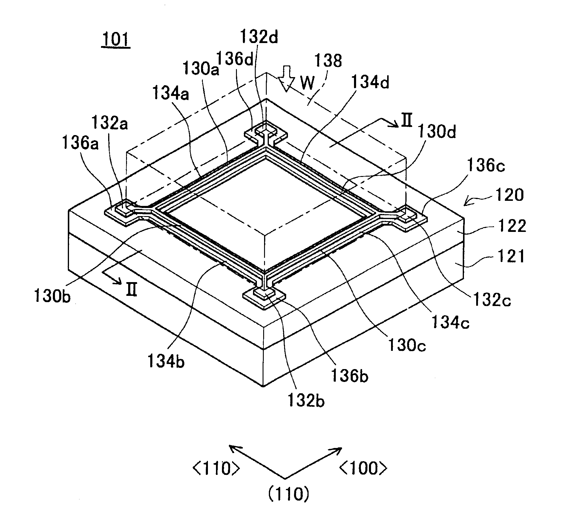
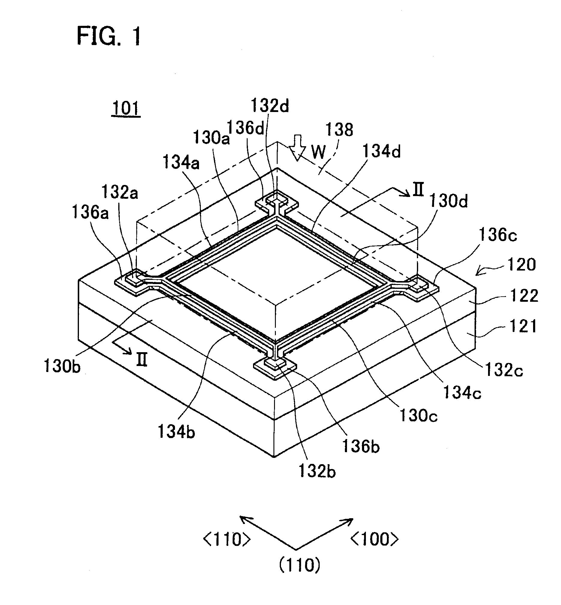
[0055]FIG. 1 shows a perspective view of a first representative force detection device (piezoresistive transducer) 101 and FIG. 2 is a cross sectional view of FIG. 1 taken along the line II—II. As shown in FIG. 1, the force detection device 101 comprises a support platform 121, a force detection block 120 and a force transmission block 138. For the sake of clarity, the force transmission block 138 is represented with dashed lines in FIG. 1.

[0056]The support platform 121 may be solid with a substantially square top surface having a width (the length of one side of the square) of about 1.4 mm and a height of about 0.5 mm. The force detection block 120 may be affixed to the upper square surface of the support platform 121.

[0057]The force detection block 120 may be formed using commercially available SOI substrates (i.e., silicon on insulator substrates) or similar materials. The force detection block 120 may include four lower and wider bases 134a, 134b, 134c, 134d that project from a ...

second representative embodiment

[0084]FIG. 8 is a cross sectional view of a second representative force detection device (piezoresistive transducer) 201, which cross sectional view corresponds to the cross sectional view shown in FIG. 2. As shown in FIG. 8, the second representative force detection device 201 includes a force detection block 220 and a force transmission block 238. Ridges 230b, 230d project from the top surface of the force detection block 220. Legs 239 extend from the bottom surface of the force transmission block 238. Although not shown in the drawings, four ridges 230a, 230b, 230c, 230d preferably form a square on the top surface of the force detection block 220. Further, four legs 239a, 239b, 239c, 239d preferably form a square having the same size on the bottom surface of the force transmission block 238. The top faces of the ridges 230 may be adhered or affixed to the bottom surfaces of the legs 239, similar to the first representative embodiment discussed above.

[0085]Each ridge 230b, 230d ma...

third representative embodiment

[0089]FIG. 9 is a perspective view of a third representative force detection device (piezoresistive transducer) 301 and FIG. 10 shows a cross sectional view taken along line X—X shown in FIG. 9. As discussed above, the first representative force detection device 101 shown in FIG. 1 defines a Wheatstone bridge using the four first semiconductor layers 126a-126d. In contrast, the third representative force detection device 301 shown in FIGS. 9 and 10 has a relatively simple strain gage construction using a single first semiconductor layer 326.

[0090]Referring to FIG. 9, the force detection device 301 may include a support platform 321, a force detection block 320 and a force transmission block 338. A lower and wider base 334 may project from the main surface of the force detection block 320. First electrode bases 336a, 336b may be connected to the lower and wider base 334. First upper and narrower ridge 330 may project above the lower and wider base 334. Further, electrodes 332a, 332b ...


PUM

PropertyMeasurementUnit
heightaaaaaaaaaa
heightaaaaaaaaaa
heightaaaaaaaaaa

Abstract

Force detection devices may have high detection precision and may prevent current leakage through a strain gage 126 to the outside. For example, a force detection block 120 may include a semiconductor substrate 122, a first insulating layer 124 and a semiconductor layer 126 (strain gage). The strain gage 126 preferably includes a site where resistance changes in accordance with the stress acting thereon. The strain gage 126 preferably constitutes at least a portion of a ridge 130 projects from the surface of the force detection block 120. A force transmission block 138 may be attached to a top surface of the ridge 130. The width of the first insulating layer 124 is preferably greater than the width of the semiconductor layer 126.

Description

CROSS-REFERENCE[0001]This application claims priority to Japanese patent application serial numbers 2001-357500, 2002-031068, 2002-259220, the contents of which are hereby incorporated by reference as if fully set forth herein.BACKGROUND OF THE INVENTION[0002]1. Field of the Invention[0003]The invention relates to force detection devices, e.g., piezoresistive transducers, and methods for manufacturing the same. Such devices can detect the magnitude of a force applied to the device. The force may be applied to the device by the pressure surrounding the device or may be transmitted to the device by force transmitting mechanical members.[0004]2. Description of the Related Art[0005]U.S. Pat. No. 5,773,728 discloses related force detection devices (i.e., piezoresistive transducers). These force detection devices comprise semiconductor material (e.g., a strain gage) that changes electrical resistance in response to stress or strain applied to the semiconductor material. Generally speaking...

Claims


Application Information

Patent Timeline
Patent Type & Authority Patents(United States)
IPC IPC(8): G01B7/16G01L1/22G01L1/20G01L1/18
CPCG01L1/18G01L1/2293
Inventor OMURA, YOSHITERUMIZUNO, KENTAROTSUKADA, KOUJISAKATA, JIROFUJITSUKA, NORIO
Owner KK TOYOTA CHUO KENKYUSHO
Why Eureka
Try Eureka