Paintgun with a revolving disc for feeding paintballs

a paint gun and revolving disc technology, applied in the direction of compressed gas guns, white arms/cold weapons, weapons, etc., can solve the problems of operators hammering the shooting sights, and achieve the effect of enhancing firepower and improving the discharge rate of invention

Active Publication Date: 2005-07-12
SHENG CHIH SHENG
View PDF12 Cites 102 Cited by
  • Summary
  • Abstract
  • Description
  • Claims
  • Application Information

AI Technical Summary

Benefits of technology

[0007]It is a primary object of the invention to provide a paintgun with a revolving disc for feeding paintballs one after another into the paintball holes first. Thereafter, the paintball is carried to a discharg

Problems solved by technology

Accordingly, this structure will hamper the shooting sights of operators.
The

Method used


Image

  • Paintgun with a revolving disc for feeding paintballs
  • Paintgun with a revolving disc for feeding paintballs
  • Paintgun with a revolving disc for feeding paintballs

Examples


Embodiment Construction

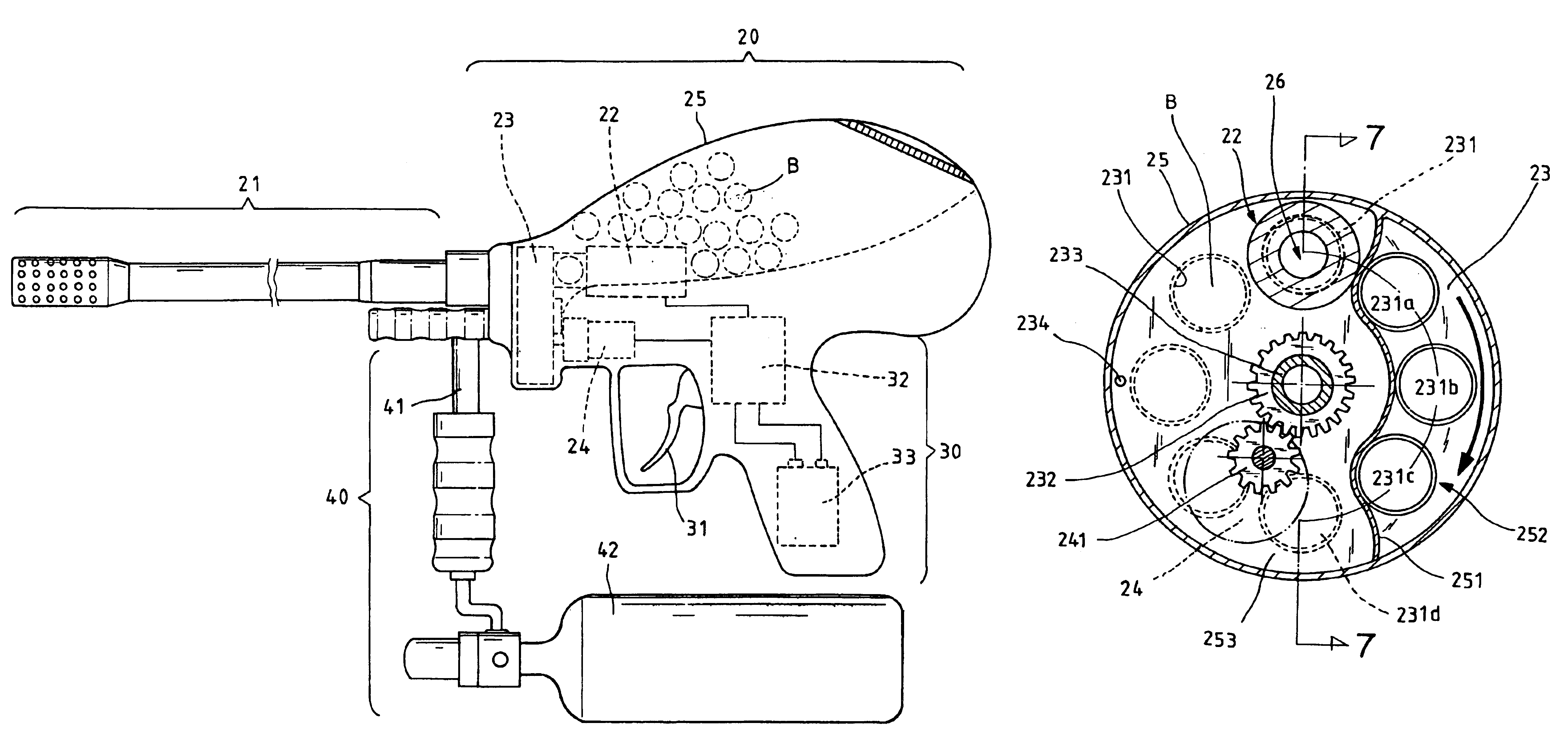
[0023]First of all, referring to FIGS. 3 and 4, an improved paintgun of the invention is shown. The paintgun in accordance with the invention mainly includes a barrel assembly 20, a trigger assembly 30 and a pneumatic delivery mechanism 40.

[0024]The barrel assembly 20 includes a barrel 21 at the front end of thereof and a firing mechanism 22 for paintballs. The trigger assembly 30 in connection with the barrel assembly 20 includes a trigger 31, a firing circuit 32 and a battery 33. The pneumatic delivery mechanism 40 includes an air inlet pipe 41 to supply pressurized air from a steel bottle 42 to the firing mechanism 22. These components have been disclosed in U.S. Pat. No. 6,601,780 so that no further descriptions are given hereinafter.

[0025]The invention features a revolving disc 23 between the barrel 21 and the firing mechanism 22. As shown in FIGS. 5 and 6, a series of 25 uniformly spaced paintball holes 231 are formed at the rim of the revolving disc 23. The revolving disc 23 ...


PUM


Abstract

The invention relates to a paintgun having a barrel assembly with a barrel and a firing mechanism for paintballs; a trigger assembly connected with the barrel assembly for actuating the firing mechanism; and a revolving disc for feeding paintballs interposed between the barrel and the firing mechanism; a series of uniformly spaced paintball holes being formed at the rim of the revolving disc that is rotatable by a driving apparatus to bring the paintballs within the paintball holes to a discharge area coaxial to the barrel for discharging the paintballs; and a paintball adjacent to the revolving disc and the firing mechanism within the barrel assembly being provided for storing the paintballs disposed. Meanwhile, the paintball container includes a guiding slope for directing the paintballs into the paintball holes. The revolving disc with the paintballs is rotatable one after another to the discharge area.

Description

BACKGROUND OF THE INVENTION[0001]1. Field of the Invention[0002]The invention relates to an improved paintgun with a revolving disc for feeding paintballs, and more particularly, to a paintgun without the problems that the paintballs are stuck, hemmed and broken. Meanwhile, a paintball container and a barrel assembly are integrated in a body so as not to restrict the shooting sights of operators.[0003]2. Description of the Related Art[0004]Paintguns in different designs have been disclosed in TW 447697, TW 443486, TW 406894, TW 437941, U.S. Pat. Nos. 6,138,656, 6,003,504, 6,532,949, etc. A paintgun, as shown in FIG. 1, has a trigger assembly 11 above which a barrel assembly 12 is disposed. The barrel assembly 12 joins a barrel 13 at the front end thereof. A filler neck 14 sitting on the barrel assembly 12 is provided for connecting a paintball container 15. A pneumatic delivery mechanism 16 is disposed beneath the barrel assembly 12.[0005]The paintball container 15 is located above ...

Claims


Application Information

Patent Timeline
IPC IPC(8): F41B11/00F41B11/02
CPCF41B11/53F41B11/54
Inventor SHENG, CHIH-SHENG
Owner SHENG CHIH SHENG
Why Eureka
Try Eureka