
Return air gasifier for charging air from bottom

A technology of gasification furnace and air intake hole, which is applied in the direction of household stove/stove, manufacture of combustible gas, lighting and heating equipment, etc. It can solve the problem of reducing the use of heat in the exhaust flue, complicated flue arrangement, and reducing combustion efficiency, etc. problems, to achieve the effects of fuel saving, good heating effect and smooth air circulation

Inactive Publication Date: 2010-06-02
张孝文
View PDF0 Cites 2 Cited by
  • Summary
  • Abstract
  • Description
  • Claims
  • Application Information

AI Technical Summary

Problems solved by technology

However, the fuel is not fully burned in the furnace, and the carbon monoxide and hydrogen generated during the period are discharged from the flue along with the smoke; the double-layer furnace is equipped with air holes, and the air can enter the furnace from the cracks of the double-layer furnace to participate in the combustion, so that the fuel is not fully burned. The carbon monoxide and hydrogen generated during combustion are used for secondary combustion, so that the utilization rate of fuel is higher, but the setting of this kind of exhaust duct is more complicated, which wastes raw materials, and the secondary air intake channel easily interferes with the exhaust duct, reducing the The use of heat by the flue; because of the existence of the double-layer furnace, the diameter of the main air intake channel will be correspondingly reduced for the same size furnace body, and the ashes after fuel combustion are easy to accumulate on the furnace bridge, blocking the air intake channel and reducing combustion. efficiency

Method used


Image

  • Return air gasifier for charging air from bottom
  • Return air gasifier for charging air from bottom

Examples


Embodiment Construction

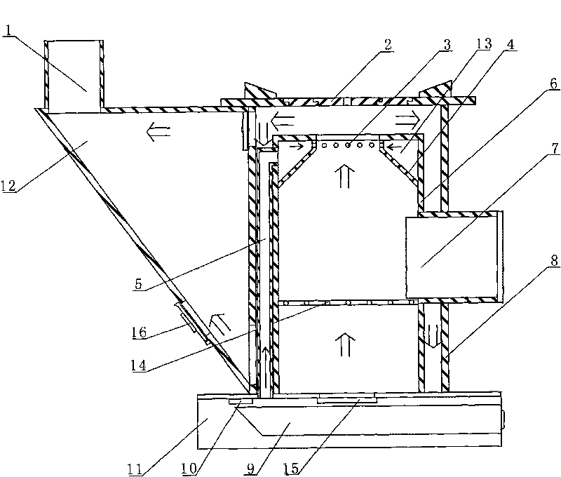
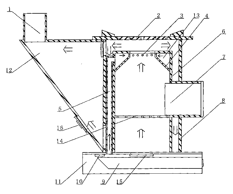
[0010] As shown in Figure 1, a return air gasifier with bottom air intake, a flue 12 is provided on one side of the furnace body 8, and the flue 12 communicates with the chimney 1, and the middle part of the furnace body 8 is provided with a feed port 7, and the bottom of the furnace body 8 A base 11 is installed, an ash bucket 9 is installed in the base 11, a smoke guide plate 2 is installed on the top of the furnace body 8, a furnace 6 is installed in the furnace body 8, a furnace bridge 14 is installed in the furnace 6, and an air inlet is provided on the top of the furnace 6 3. The furnace 6 is provided with a furnace inner plate 4, and the air inlet 3 communicates with the air intake channel 13 formed by the furnace 6 and the furnace inner plate 4. One end of the secondary air intake pipe 5 communicates with the air intake channel 13, and the other end is opened at In the base 11, a secondary air intake damper 10 is provided at the opening of the lower end of the secondary...


PUM


Abstract

The invention discloses a return air gasifier for charging air from the bottom and relates to a civil stove. An air inlet channel is arranged on the top of a hearth, one end of a secondary air inlet pipe is communicated with the air inlet channel, and an opening at the other end is arranged in a base. The opening is provided with a secondary air inlet door, and an opening at the lower end of the hearth is provided with a main air door. The secondary air inlet door is linked with the main air door, namely when the main air door is opened, the secondary air inlet door is closed, and when the secondary air inlet door is opened, the main air door is closed. A return air stove state and a gasifier state can be conveniently switched, thus the invention has the advantages of large firepower of the return air stove and high utilization rate of the gasifier. The secondary air inlet door arranged at the bottom is convenient to open and close and cannot influence the appearance of the stove, the smoke discharge of a flue and the diameter of the hearth, thus ventilation in the hearth is smooth. The invention also has the advantages of fuel saving, high burning efficiency, large firepower and good heating effect.

Description

technical field [0001] The invention relates to a civil stove, in particular to a return air gasification furnace with bottom air intake. Background technique [0002] The stoves currently in use generally use a single-layer or double-layer furnace. The flue exhaust of the single-layer furnace is ideally arranged, and the long-distance flue of the loop can make better use of the heat of the fuel. However, the fuel is not fully burned in the furnace, and the carbon monoxide and hydrogen generated during the period are discharged from the flue along with the smoke; the double-layer furnace is equipped with air holes, and the air can enter the furnace from the cracks of the double-layer furnace to participate in the combustion, so that the fuel is not fully burned. The carbon monoxide and hydrogen generated during combustion are used for secondary combustion, so that the utilization rate of fuel is higher, but the setting of this kind of exhaust duct is more complicated, which ...

Claims


Application Information

Patent Timeline
Patent Type & Authority Applications(China)
IPC IPC(8): F24B1/19C10J3/22
Inventor 张孝文
Owner 张孝文
Learn More