Bottle stopper

a bottle neck and bottle cap technology, applied in the field of bottle caps, can solve the problems of wet and aged corks that tend to disintegrate, the plug is difficult to be remained in the bottle neck, and the bottle neck is difficult to be inserted in the bottle neck in the bottling process

Inactive Publication Date: 2005-07-12
SUNLOT BOTTLE STRPPER
View PDF10 Cites 23 Cited by
  • Summary
  • Abstract
  • Description
  • Claims
  • Application Information

AI Technical Summary

Benefits of technology

[0010]The secondary objective of this invention is to provide a bottle stopper with an obstructer which can prevent from an accidental press of a plug.

Problems solved by technology

In particular, the plug is hard to be remained in the bottle neck by an axially directed inner pressure from within the bottle.
However, the plug necessitates to tightly seal the bottle neck and thus it is hard to be inserted into the bottle neck in the bottling process.
In addition, wet and aged cork tends to disintegrate and it is often difficult to remove from the bottle neck.
Accordingly, it is inconvenient to remove the cork when it is easily snapped in two.
There is a serious problem in the market.
However, such bottle plug's elements cannot be made of glass, crystal, ceramic or manufactured various designs of bottle head.

Method used


Image

  • Bottle stopper
  • Bottle stopper
  • Bottle stopper

Examples


first embodiment

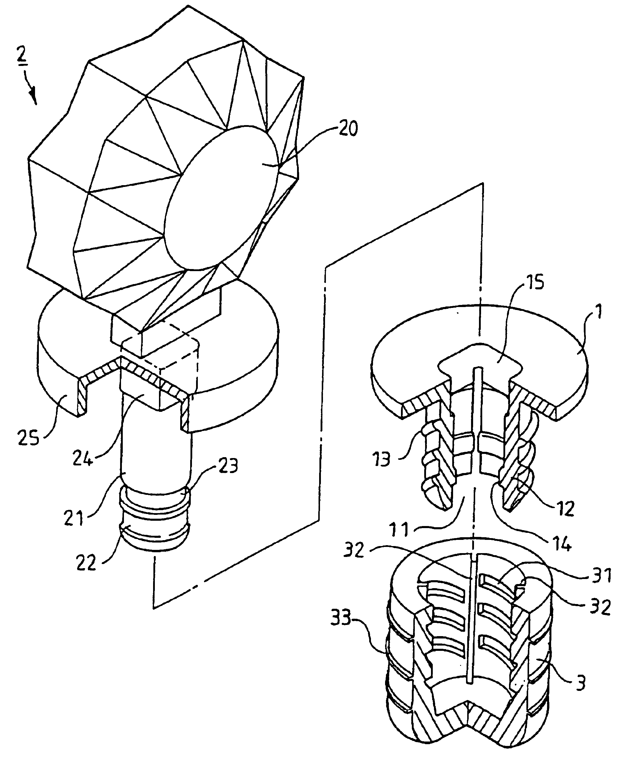
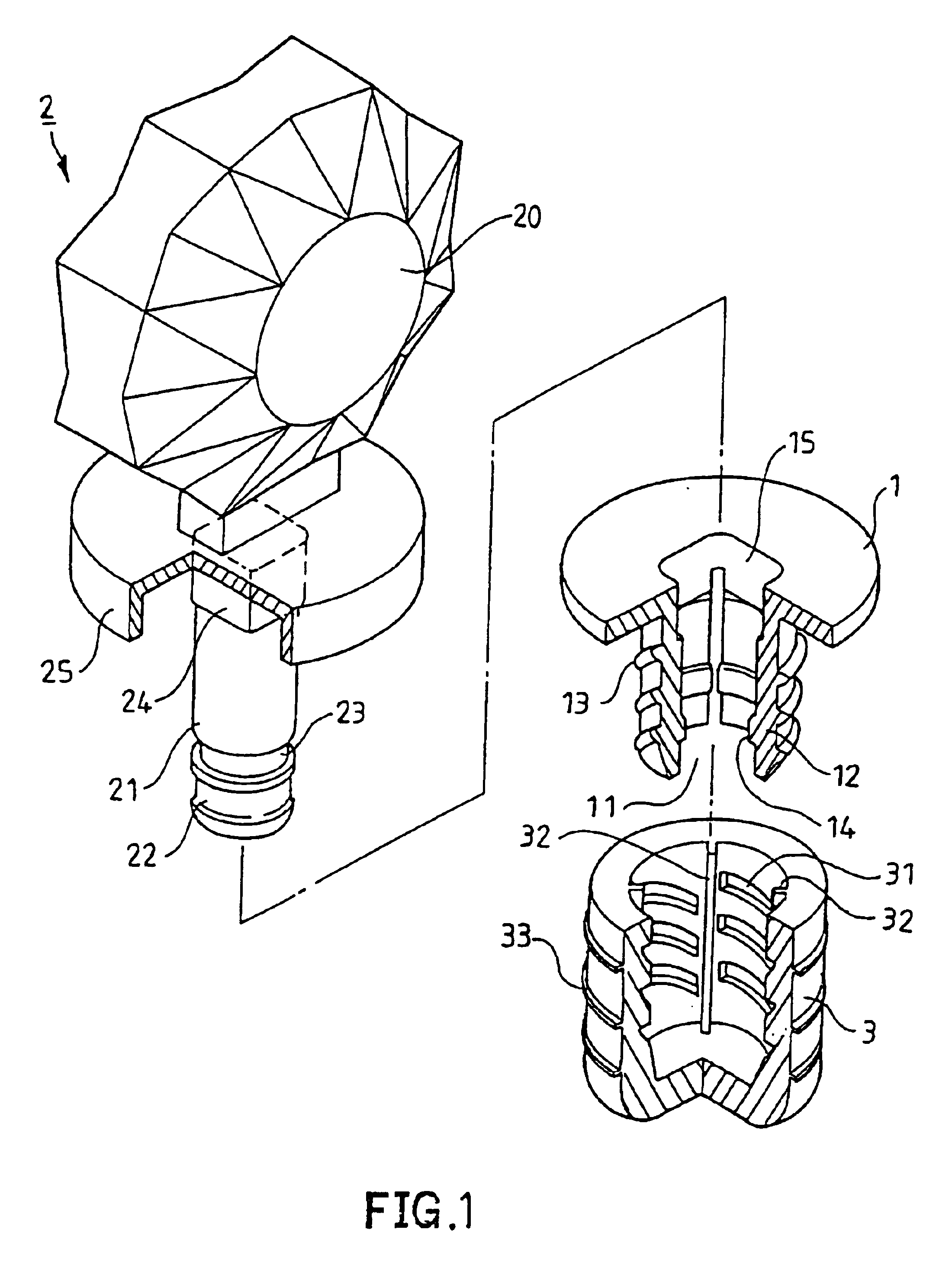
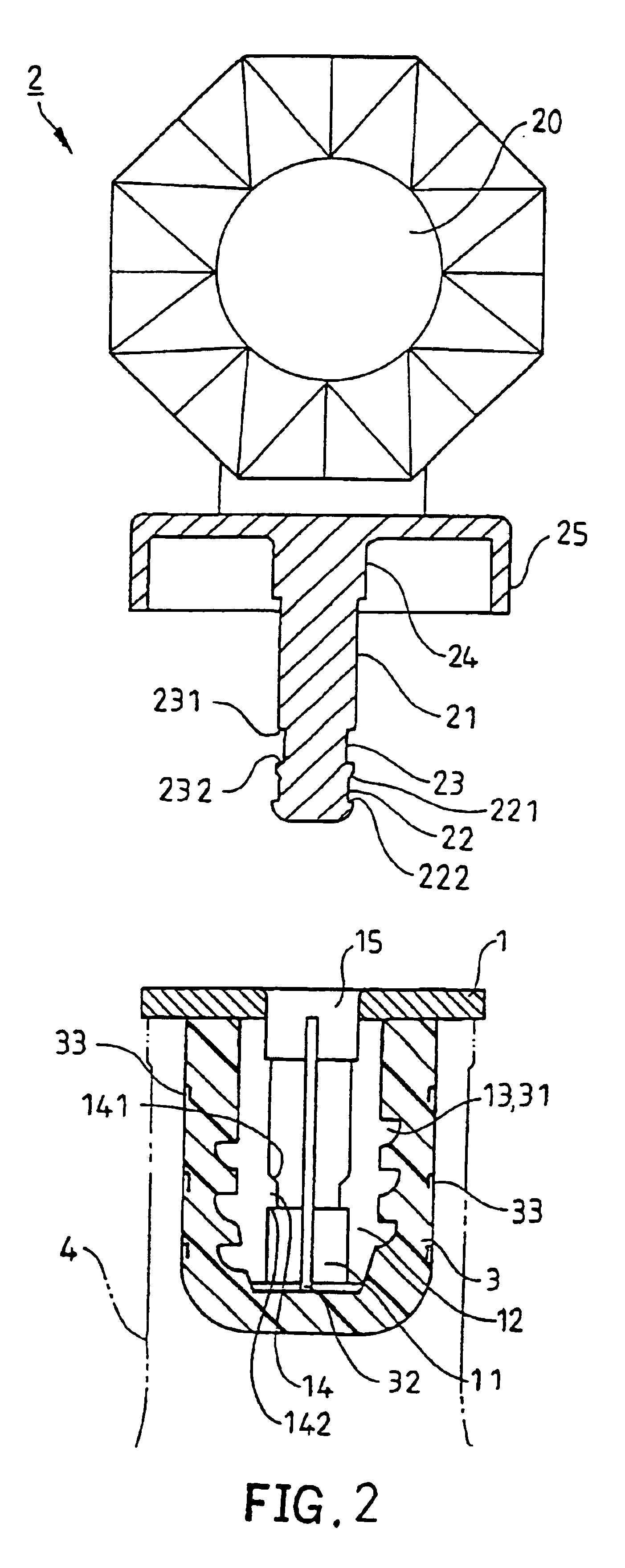
[0037]Referring to FIG. 1, a bottle stopper in accordance with the present invention mainly includes a body generally designated as numeral 1, a plug as numeral 2 and a jacket as numeral 3. Referring to FIGS. 1 and 2, the body 1 is made of plastic material and includes an opening 15 formed on its top and a plurality of flexible walls 12 projected downward from the top and encircled an axis to define a space with an opening 11. The inner circumference of each flexible wall 12 provides a slightly protrusion 14 projecting inwardly in a common plane perpendicular to the axis defined by the body 1. The outer circumference of each flexible wall 12 further provides a plurality of screwing ribs 13 projecting outwardly and encircling co-axially around the axis of the body 1. The plug 2 is essentially consisted of a head 20 and a leg 21 combined by adhesive. The head is made of crystal, glass, ceramic or the like. The preferred shape of the head 20 is dictated somewhat by tradition and etique...

second embodiment

[0041]FIG. 5 illustrates the bottle stopper of the present invention mainly comprising a body 1, an ornamental ring 16, a plug 2 and a jacket 3.

[0042]Referring to FIG. 5, reference numerals of the second embodiment has applied the identical numerals of the previous embodiment. The body 1, the plug 2 and the jacket 3 of the second embodiment have the similar configuration and same functions as the previous embodiment and the detailed descriptions are omitted. The ornamental ring 16 with an appropriate recess provides a circular edge receiving the top of the body 1 and a central opening for allowing the walls 12 of the body 1 extending through to combine with the jacket 3. The ornamental ring 16 is made of crystal, glass, metal or ceramic with the same as that of the plug 2 or bottle. The bottle stopper further comprises a gasket 26 having a base 261 and two tear line 262. The gasket 26 is received in the recess of the ornamental ring 16 to obstruct further advance of the leg 21 with ...

third embodiment

[0047]FIG. 10 illustrates the bottle stopper in accordance with the present invention in a step for releasing and resealing bottle neck. Referring again to FIG. 10, the flange 17 has been torn off along the tear line 18 and the plug 2 is pressed downward to form a resealing means, when the second neck 23 is engaged with the protrusion 14. The releasing means provides a slight expansion which diameter is relatively smaller than that of the locking means for allowing to initially release the bottle neck 4. The plug 2 with a tore appearance indicates that the stopper has been used and the bottle neck 4 has previously opened.

[0048]FIG. 11 illustrates the bottle stopper of the fourth embodiment of the present invention mainly comprising a body 1, a plug 2 and a jacket 3. Referring to FIG. 11, reference numerals of the fourth embodiment has applied the identical numerals of the first embodiment. The body 1, the plug 2 and the jacket 3 of the similar embodiment have the similar configurati...


PUM

PropertyMeasurementUnit
flexibleaaaaaaaaaa
diameteraaaaaaaaaa
circumferenceaaaaaaaaaa

Abstract

A bottle stopper mainly includes a body, a plug and a jacket. The body has an expansion spread by the plug and outwardly confronting with the jacket. The plug comprises two necks for two different engagements alternatively engaged with the body to provide a locking means and a resealing means for bottle neck. The body is structurally retained between the plug and the jacket being assembled as a unit to form the bottle stopper. When the bottle stopper is initially inserted into a bottle neck and pressed to position at the first engagement, the locking means provides a maximum expansion to lock around the bottle neck. And it has an appearance and a function of indicating whether the bottle neck has previously opened or the stopper has been used. When the bottle stopper is pressed downward positioning at the second engagement, the resealing means provides a slightly expansion for allowing to initially release and reseal the bottle neck.

Description

BACKGROUND OF THE INVENTION[0001]1. Field of the Invention[0002]The present invention is related to a bottle stopper for conveniently inserting into bottle neck, completely sealing it and preventing from unlawful reuse in closing process, and more particularly to the bottle stopper for using to reseal bottle neck opened.[0003]2. Description of the Related Art[0004]Liquor, wine or the like is conventionally contained in glass or ceramic bottle. Before the bottling process, distilled heat liquor has already situated in high inner pressure. In the bottling process, when the traditional plug is typically forced into the neck of a filled bottle, the inner pressure in the filled bottle is essentially greater than atmospheric pressure. Typically, the diameter of plug is apt to slightly greater than the inner circumference of the bottle neck in order to sealably confront each other when the plug is axially inserted into the bottle neck. The plug, therefore, is capable of withstanding substa...

Claims


Application Information

Patent Timeline
Patent Type & Authority Patents(United States)
IPC IPC(8): B65D39/12B65D39/00B65D39/16
CPCB65D39/0076B65D39/12B65D39/16
Inventor HWANG, HSU-RONGLIN, SEN-YIH
Owner SUNLOT BOTTLE STRPPER
Why Eureka
Try Eureka