Fuel injector

a fuel injector and injector technology, applied in the direction of fuel injecting pumps, liquid fuel feeders, machines/engines, etc., can solve the problems of eccentric injection holes, easy to obtain desired spray, and decentering of injection holes, etc., to achieve the effect of easy adjustment of spray shap

Inactive Publication Date: 2005-07-12
HITACHI LTD +1
View PDF8 Cites 8 Cited by
  • Summary
  • Abstract
  • Description
  • Claims
  • Application Information

AI Technical Summary

Benefits of technology

[0009]The object of the present invention is to provide a fuel injector that enables the injection direction of fuel and the shape of its spray to be easily adjusted.
[0011]It is also possible, by providing, at the upstream side of the swirling force adjustment means, an injection volume measuring portion which functions as a fuel passageway whose cross-sectional area is the smallest of all other sections, and so it is easy to adjust the spray shape.
[0012]A further object of the present invention is to supply a fuel injector that enables the injection direction of fuel and the shape of its spray to be adjusted.
[0013]In a fuel injector that has an injection hole for injecting fuel and which imparts a swirling force to the fuel from the upstream side of the injection hole, a valve seat, a valve member for opening and closing a fuel passageway between the injection hole and the valve seat, and a means for driving the valve member, a swirling force adjustment means for adjusting the swirling force that has been imparted by said swirling force impartment means is provided in the fuel passageway and ranges from the valve seat to the injection hole. The use of the swirling force impartment means enables the desired spray shape to be obtained by adjusting the swirling force of the fuel flowing into the injection hole.
[0015]In addition, it is possible, by providing, at the upstream side of the swirling force adjustment means, an injection volume measuring portion which functions as a fuel passageway whose cross-sectional area is the smallest of all other sections', to independently adjust both the spray shape of the fuel and the volume of injection thereof, so that it is easy to adjust the spray shape.

Problems solved by technology

For example, there is a problem in that the inclination of the fuel injection direction also causes an offset in the concentration distribution of the fuel, and the desired spray is not easy to obtain.
Therefore, there is a problem in that the decentering of the injection hole changes the volume of the fuel injection.
Conversely, if the diameter of the injection hole is changed to compensate for a change in injection volume, the amount of eccentricity of the injection hole will also change, which will make it difficult to obtain both the desired injection volume and spray shape.
In addition, it is not easy to provide an inclined injection hole in a curved fuel injection chamber by simply piercing, in eccentric form, the member constituting the injection hole, or to provide a member that has an inclined and eccentric injection hole, with curved-surface machining appropriate for the fuel injection chamber; and so, the use of these machining processes causes an increase in cost when the fuel injector is to be manufactured by mass production.

Method used


Image

  • Fuel injector
  • Fuel injector
  • Fuel injector

Examples


Embodiment Construction

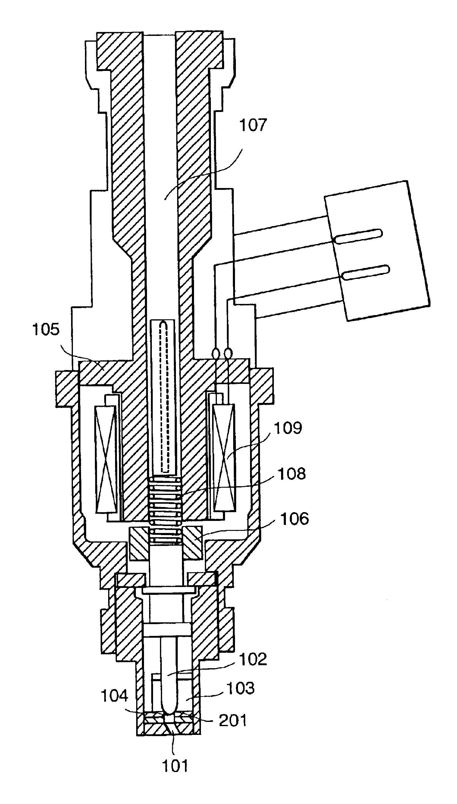
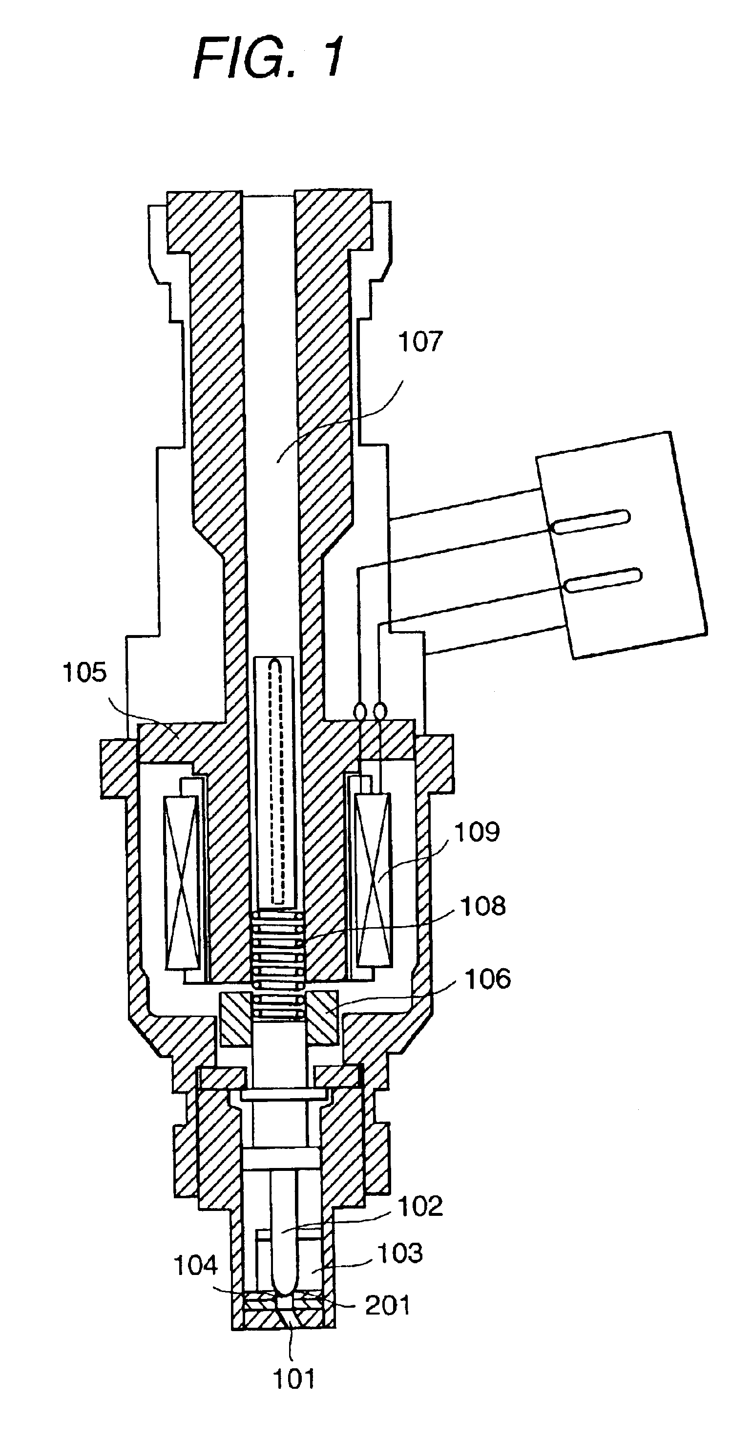
[0028]FIG. 1 is a cross-sectional view showing the structure of a fuel injector in accordance with an embodiment of the present invention. The fuel injector shown in FIG. 1 is a normally closed type of fuel injector, wherein, when a coil 109 is not energized, a valve member 102 is in firm contact with a valve seat 201 to prevent the flow of fuel therethrough. Fuel is supplied from a fuel supply port under pressure which is imparted by a fuel pump (not shown in the figure), and the section from a fuel passageway 107 to the point of firm contact between the valve member 102 and the valve seat 201 is filled with fuel. When the coil 109 is energized and valve member 102 is moved away from the valve seat 201 by the longitudinal displacement of the valve member 102, the fuel will be injected through an injection hole 101. Since the fuel is passed to the injection hole 101 through the swirling grooves of a swirling element 103 at that time, a swirling force is imparted to the fuel during i...


PUM


Abstract

To enable the inclination of the injection direction and the distribution of the penetration force of spray to be adjusted over a wide range, and an axially symmetrical spray shape to be obtained even when the injection hole is inclined, or the shape of the spray to be changed without inclining the injection hole, a fuel passageway 203 is provided as a swirling force adjustment means between the valve seat 201 and injection hole 101 of the fuel injector. This swirling force adjustment means adjusts the distribution of the swirling force of the fuel flowing into injection hole 101, and thus adjusts the spray shape obtained as a result.

Description

BACKGROUND OF THE INVENTION[0001]The present invention relates to fuel injectors of the type used in an internal combustion engine.[0002]Japanese Application Patent Laid-Open Publication No. Hei 08-42427 discloses a fuel injector for an internal combustion engine, in which a valve member slidable in its axial direction is provided inside a body having a cross-sectionally round injection hole as an open end. A swirling force generating means for imparting a swirling component to fuel is disposed between the outer surface of the valve member and the inner surface of the body. The base end portion of the injection hole is open on the axial center line of the injector, but the open edge of the front open end of the injection hole is not disposed along a plane orthogonal to the center line of the injection hole. More specifically, the open edge of the front open end of the injection hole in the fuel injector is disposed along a plane that is inclined with respect to the center line of th...

Claims


Application Information

Patent Timeline
Patent Type & Authority Patents(United States)
IPC IPC(8): F02M51/06F02B75/12F02M69/00F02M69/04F02M61/16F02M61/18
CPCF02M61/188F02M61/18F02M2200/9038F02M45/08F02M61/186F02B2075/125F02M69/045Y02T10/123F02M61/1806Y02T10/125F02B23/104F02M51/0671F02M61/168F02M61/162Y02T10/12
Inventor ABE, MOTOYUKIOKAMOTO, YOSHIOYAMAKADO, MAKOTOISHIKAWA, TOHRUSHIMIZU, SHUICHI
Owner HITACHI LTD
Why Eureka
Try Eureka