Two-group zoom lens

a zoom lens and two-group technology, applied in the field of two-group zoom lenses, can solve the problems of high zoom ratio and inability to clearly focus images, and achieve the effects of reducing aberration, comparatively bright imaging, and favorable correction of aberrations

Active Publication Date: 2005-07-12
FUJI PHOTO OPTICAL CO LTD
View PDF7 Cites 22 Cited by
  • Summary
  • Abstract
  • Description
  • Claims
  • Application Information

AI Technical Summary

Benefits of technology

[0003]The present invention is a compact, two-group zoom lens that favorably corrects aberrations in both the visible region and the near infrared region and provides comparatively bright imaging while providing a higher zoom ratio than has conventionally been available. The present invention is particularly suited for surveillance imaging.

Problems solved by technology

Although many zoom lenses have been designed for use in the visible light region, conventional zoom lenses especially designed for use in the visible region generate substantial chromatic aberrations in the near infrared region, which cause images to not be clearly focused when imaging at night using the near infrared region.
However, there is a demand for a zoom lens with a higher zoom ratio and that remains compact.

Method used


Image

  • Two-group zoom lens
  • Two-group zoom lens
  • Two-group zoom lens

Examples


embodiment 1

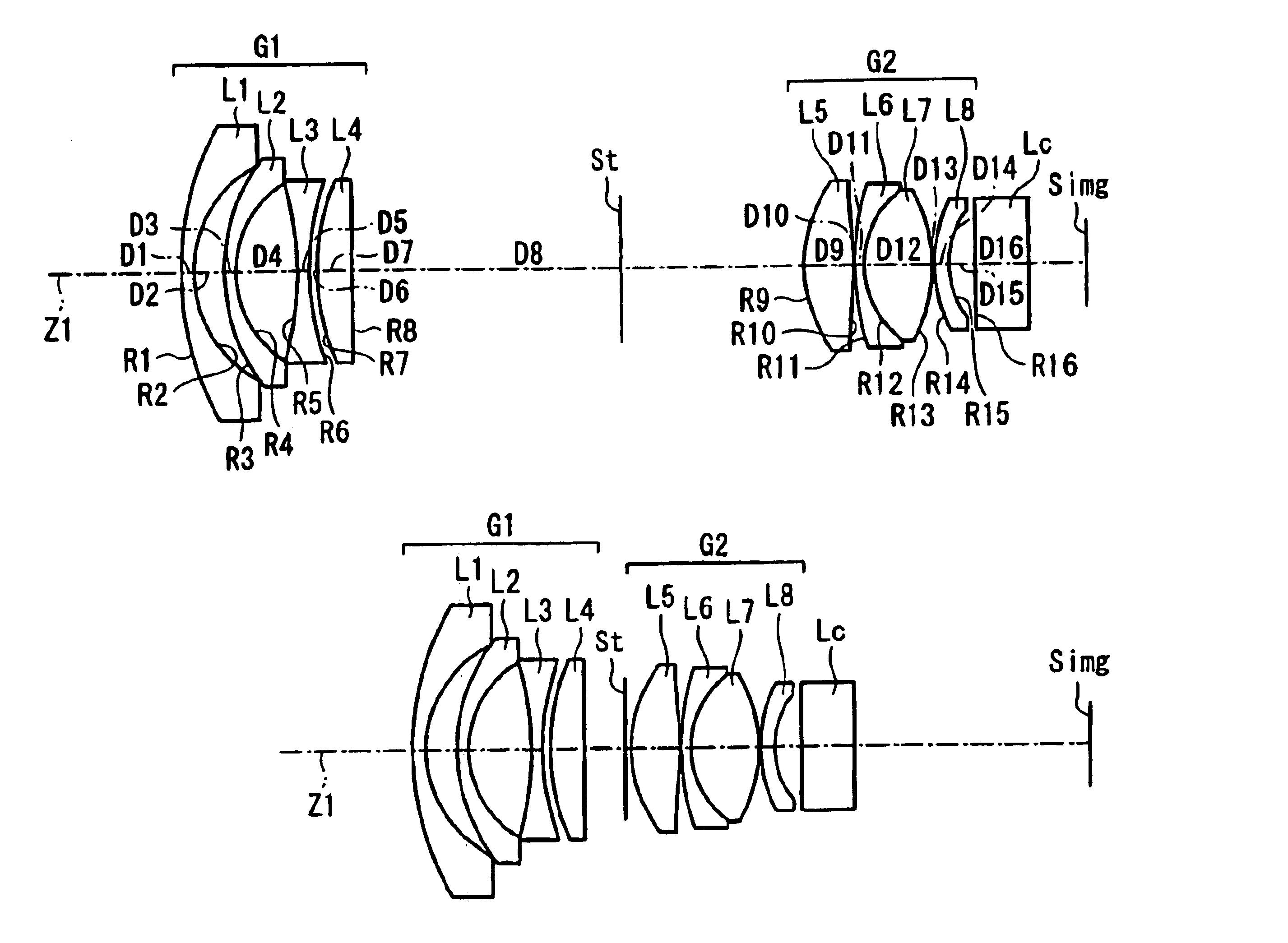
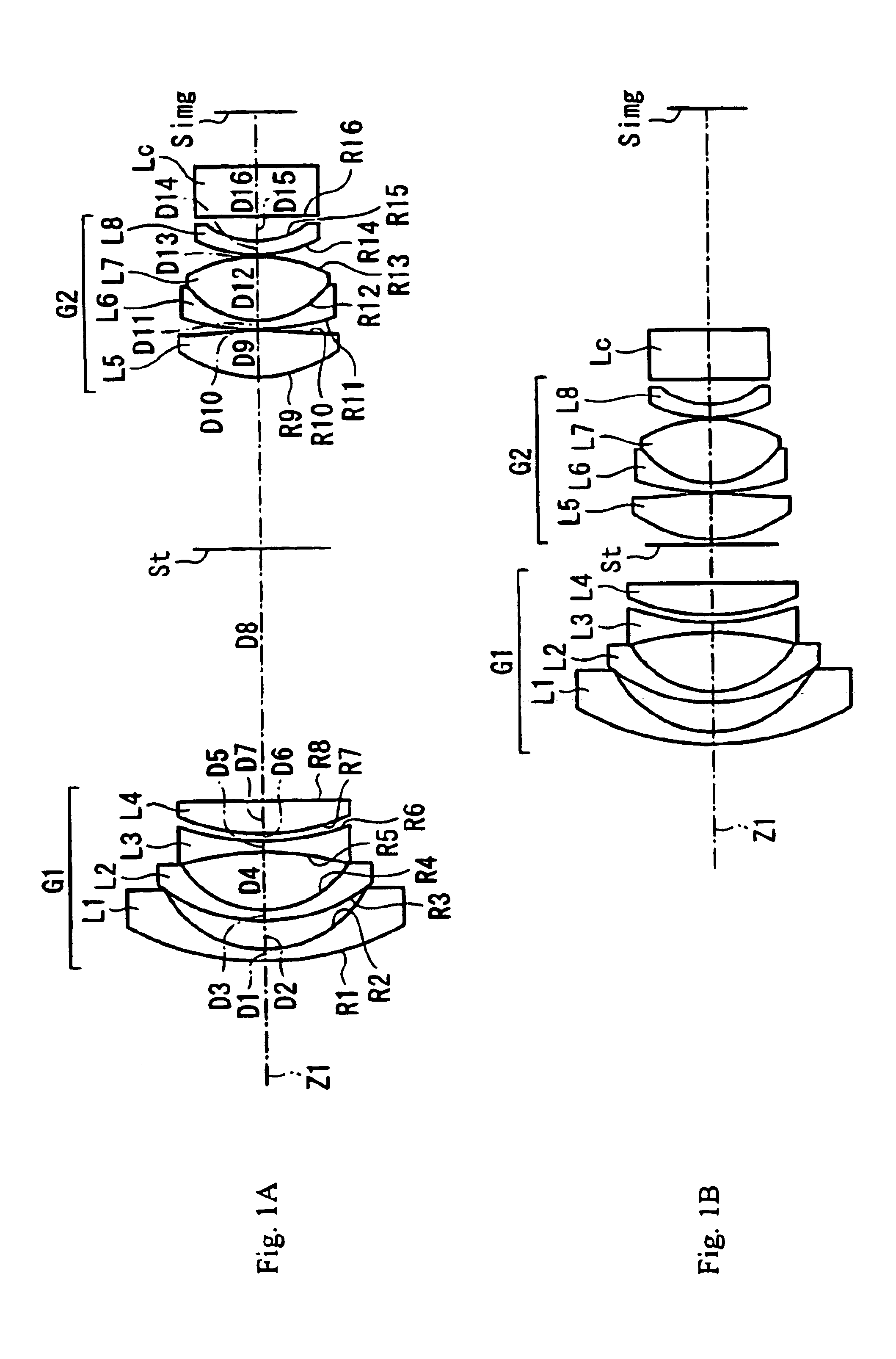
[0045]Table 1 below lists the surface number #, in order from the object side, the radius of curvature R (in mm) of each surface near the optical axis, the on-axis surface spacing D (in mm), as well as the refractive index Nd and the Abbe number vd (both at the d-line of 587.6 nm) of each lens element for Embodiment 1.

[0046]

TABLE 1#RDNdνd 123.041.001.7725049.6 29.262.37 313.940.901.7550052.3 48.004.78 5−25.390.901.7129953.8 620.120.59 717.252.641.8466523.8 81107.40D8 (variable) 9*9.873.761.5686758.2 10*−27.770.101119.110.801.8060933.3127.425.121.4970081.513−12.130.101411.211.101.8051725.4156.632.0016∞4.001.5168064.2The lens surfaces with a * to the right of the surface number in Table 1 are aspheric lens surfaces, and the aspheric surface shape of these lens elements is defined using Equation (A) above.

[0047]Table 2 below lists the values of the constants K, A4, A6, A8, and A10 used in Equation (A) above for each of the aspheric surfaces indicated in Table 1. Aspheric coefficients ...

embodiment 2

[0054]Embodiment 2 is very similar to Embodiment 1 and therefore only the differences between Embodiment 2 and Embodiment 1 will be explained. Embodiment 2 differs from Embodiment 1 in its lens element configuration such as different radii of curvature of lens surfaces, different eccentricities and aspheric coefficients of the aspheric lens surfaces, some different optical element surface spacings, some different refractive indexes, and some different Abbe numbers of the optical materials of the lens elements.

[0055]Table 5 below lists the surface number #, in order from the object side, the radius of curvature R (in mm) of each surface near the optical axis, the on-axis surface spacing D (in mm), as well as the refractive index Nd and the Abbe number vd (both at the d-line of 587.6 nm) of each lens element for Embodiment 2.

[0056]

TABLE 5#RDNdνd 125.311.001.8160046.6 210.851.87 317.210.901.8348042.7 47.824.65 5−22.360.901.7129953.8 642.970.10 719.102.551.8466523.8 8−646.83D8 (variable...

embodiment 3

[0064]Embodiment 3 is very similar to Embodiment 1 and therefore only the differences between Embodiment 3 and Embodiment 1 will be explained. Embodiment 3 differs from Embodiment 1 in its lens element configuration such as different radii of curvature of lens surfaces, different eccentricities and aspheric coefficients of the aspheric lens surfaces, some different optical element surface spacings, some different refractive indexes, and some different Abbe numbers of the optical materials of the lens elements.

[0065]Table 9 below lists the surface number #, in order from the object side, the radius of curvature R (in mm) of each surface near the optical axis, the on-axis surface spacing D (in mm), as well as the refractive index Nd and the Abbe number vd (both at the d-line of 587.6 nm) of each lens element for Embodiment 3.

[0066]

TABLE 9#RDNdνd 124.571.001.7725049.6 29.501.96 312.760.901.7858944.2 47.734.88 5−26.560.901.7725049.6 624.560.36 717.362.591.8466523.8 8427.90D8 (variable) ...


PUM


Abstract

A compact two-group zoom lens that corrects aberrations in the visible and the near infrared regions and that provides a comparatively high zoom ratio includes, in order from the object side, a first lens group of negative refractive power and a second lens group of positive refractive power. The first lens group includes, in order from the object side, first and second negative meniscus lens elements having convex surfaces on the object side, a biconcave lens element, and a positive lens element. The second lens group includes, in order from the object side, a positive lens component which may be a lens element, a negative/positive doublet component, and a negative lens component which may be a lens element. Aspheric lens surfaces are disclosed. Certain conditions are satisfied to control aberrations in both the visible and the near infrared and to ensure a sufficient back focus distance.

Description

[0001]Cameras for both day and night use have been developed for surveillance imaging. Additionally, the demand for lenses that operate in both the visible light region and the near infrared region for use both during the day and at night has been increasing. Although many zoom lenses have been designed for use in the visible light region, conventional zoom lenses especially designed for use in the visible region generate substantial chromatic aberrations in the near infrared region, which cause images to not be clearly focused when imaging at night using the near infrared region.[0002]Zoom lenses for use in both the visual region and in the near infrared region are described in Japanese Laid-Open Patent Application 2002-196235, Japanese Laid-Open Patent Application 2002-207166, and Japanese Laid-Open Patent Application 2002-244038. The zoom lenses described in these applications are formed with only two lens groups, are relatively compact, and provide a zoom ratio of about 2.2. How...

Claims


Application Information

Patent Timeline
Patent Type & Authority Patents(United States)
IPC IPC(8): G02B15/177
CPCG02B15/177G02B15/1425
Inventor TAKATSUKI, AKIKO
Owner FUJI PHOTO OPTICAL CO LTD
Why Eureka
Try Eureka