
Optical fiber, optical transmission line, and optical communications system

a technology of optical communication system and optical transmission line, which is applied in the direction of cladded optical fibre, optical fibre with desired dispersion, instruments, etc., can solve the problems of insufficient chromatic dispersion absolute value in the l-band, inability to perform wdm optical communication in the l-band, and difficulty in reducing the absolute value of chromatic dispersion over the entire wavelength band of the signal

Active Publication Date: 2005-07-12
SUMITOMO ELECTRIC IND LTD
View PDF6 Cites 17 Cited by
  • Summary
  • Abstract
  • Description
  • Claims
  • Application Information

AI Technical Summary

Benefits of technology

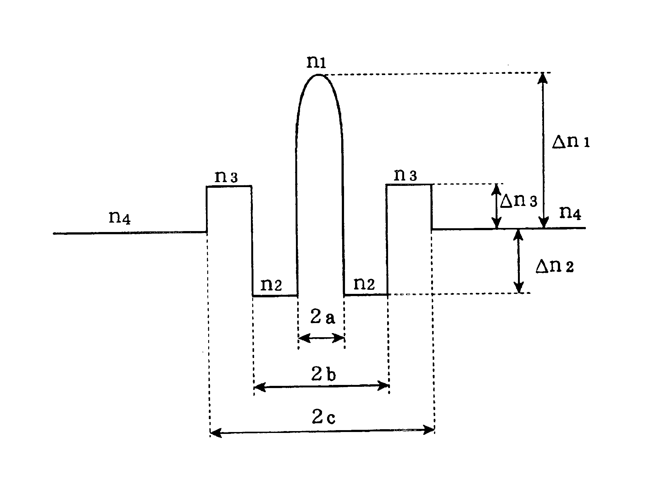
The present invention offers an optical fiber that can compensate for both chromatic dispersion and dispersion slope in a non-zero dispersion-shifted fiber. This optical fiber has a unique structure that includes a central core region, first and second cladding regions, and third and fourth cladding regions. An optical transmission line is also provided that includes this optical fiber spliced with a positive-dispersion optical fiber. The optical fiber can be used in an optical communications system to transmit high-quality WDM optical signals in the L-band. The technical effects of the invention include improved optical signal quality, reduced signal loss, and improved transmission distance.

Problems solved by technology

However, it is difficult to reduce the absolute value of the chromatic dispersion over the entire wavelength band of the signal lightwave when the optical transmission line is constructed by using only one type of optical fiber.
However, the absolute value of the chromatic dispersion is not sufficiently small in the L-band.
Therefore, they are not suitable for performing WDM optical communication in the L-band.
However, no report has so far been published on a dispersion-compensating optical fiber capable of compensating in the L-band both the chromatic dispersion and dispersion slope of the above-described non-zero dispersion-shifted fibers.

Method used


Image

  • Optical fiber, optical transmission line, and optical communications system
  • Optical fiber, optical transmission line, and optical communications system
  • Optical fiber, optical transmission line, and optical communications system

Examples


Embodiment Construction

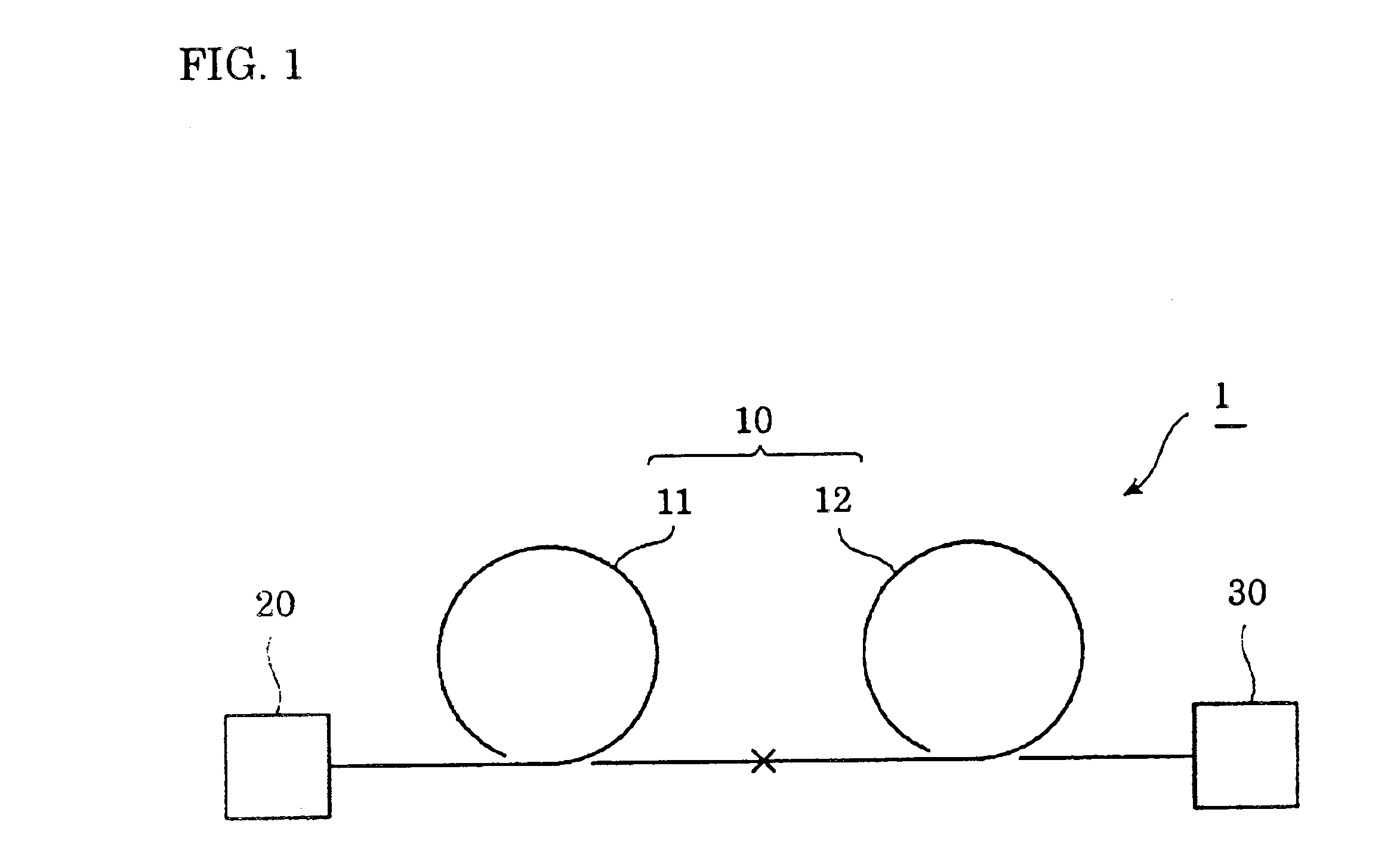
[0034]FIG. 1 is a diagram showing the constitution of an optical communications system 1 and an optical transmission line 10 in the embodiment of the present invention. The optical communications system 1 comprises an optical transmission line 10, an optical transmitter 20, and an optical receiver 30. The optical transmitter 20 multiplexes a plurality of component signals having mutually different wavelengths to output them. A wavelength-multiplexed signal lightwave travels over the optical transmission line 10. The optical receiver 30 receives the signal lightwave. The optical transmission line 10 comprises an optical fiber 11 and an optical fiber 12 that are mutually fusion-spliced. The signal lightwave travels over the optical fibers 11 and 12 in this order.

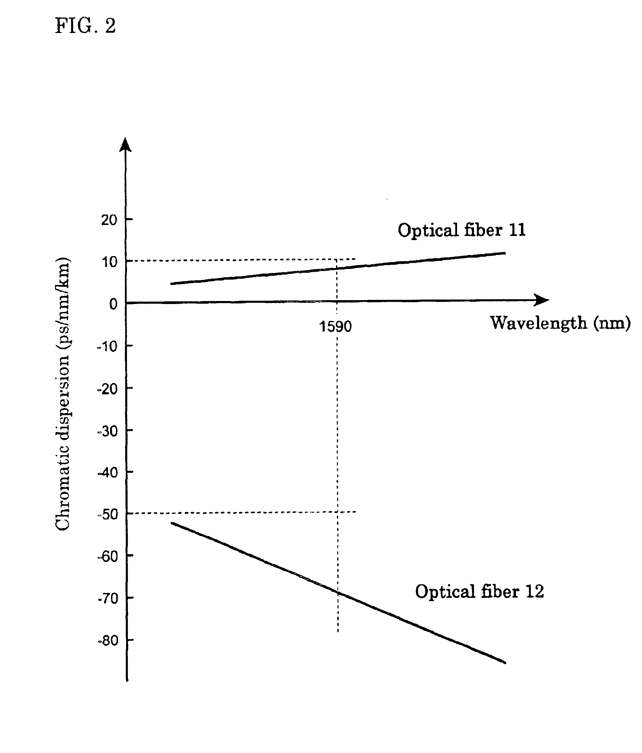
[0035]FIG. 2 is a graph showing the chromatic dispersion-wavelength properties of the optical fibers 11 and 12. The optical fiber 11 has a positive chromatic dispersion and a positive dispersion slope at a wavelength of 1,590 ...


PUM


Abstract

An optical fiber capable of compensating in the L-band both the chromatic dispersion and dispersion slope of a positive-dispersion optical fiber, an optical transmission line incorporating the optical fiber, and an optical communications system incorporating the optical transmission line. An optical communications system 1 comprises an optical transmission line 10, an optical transmitter 20, and an optical receiver 30. The optical transmission line 10 comprises an optical fiber 11 and an optical fiber 12 that are mutually fusion-spliced. The optical fiber 12 has at a wavelength of 1,590 nm a chromatic dispersion, D2, and a dispersion slope, S2, that satisfy the formulae −200 ps / nm / km≦D2≦−50 ps / nm / km, and 0.009 / nm≦S2 / D2.

Description

BACKGROUND OF THE INVENTION[0001]1. Field of the Invention[0002]The present invention relates to an optical fiber capable of compensating both the chromatic dispersion and dispersion slope of a positive-dispersion optical fiber, an optical transmission line constructed by splicing the optical fiber and a positive-dispersion optical fiber, and an optical communications system incorporating the optical transmission line.[0003]2. Description of the Background Art[0004]The wavelength division multiplexing (WDM) optical communications system multiplexes a plurality of component signals having mutually different wavelengths with an optical transmitter to transmit them. A signal lightwave composed of the component signals travels over an optical transmission line to arrive at an optical receiver. The WDM communications system can transmit and receive a large volume of information at a high rate. The conventional WDM communications system uses the C-band (1,530 to 1,565 nm) as a wavelength ...

Claims


Application Information

Patent Timeline
Patent Type & Authority Patents(United States)
IPC IPC(8): G02B6/036G02B6/028G02B6/02G02B6/34
CPCG02B6/02009G02B6/02261G02B6/0228G02B6/03644G02B6/29376G02B6/02271G02B6/29377
Inventor HONMA, NORITAKAKATO, TAKATOSHI
Owner SUMITOMO ELECTRIC IND LTD
Learn More