Threading device of sewing machine

a threading device and sewing machine technology, applied in sewing apparatus, needle bars, textiles and paper, etc., can solve the problems of inconvenient threading operation, high cost, and high complexity of the device disclosed in the japanese patent application, and achieve the effect of smooth disengagement from the threading hook, smooth threading operation, and simple structur

Active Publication Date: 2005-07-19
JANOME CORP
View PDF2 Cites 10 Cited by
  • Summary
  • Abstract
  • Description
  • Claims
  • Application Information

AI Technical Summary

Benefits of technology

[0007]It is, therefore, a principal object of the invention to provide a threading device of sewing machine which may be easily operated to guide the upper thread into engagement with a thread holder in the process of needle threading operation.
[0008]It is another object of the invention to provide a threading device of sewing machine which is simple in structure and smooth in operation.
[0012]According to the invention, the upper thread may be smoothly and exactly guided into engagement with the thread holder simultaneously when the upper thread is passed through the needle eye. The threading device of the invention is simple in structure and is not an obstacle to the other parts of sewing machine. The threading device includes a thread guide wall having a lower end side extending progressively lower from the lateral free end side to the swing center of the thread guide wall such that the upper thread may be guided into the upper guide.
[0013]The upper thread is passed through the needle eye in a form of loop which is progressively enlarged as the threading hook is moved up. The thread loop may be smoothly disengaged from the threading hook when the threading loop becomes a predetermined size. Further the swelled protrusion is extended along the lower end side of the thread guide wall and is progressively reduced from the lateral free end side to the swing center of the thread guide wall so that the threading operation may be smoothly and exactly performed.

Problems solved by technology

However, in fact, it is considerably difficult to manually hang the upper thread onto the thread holder.
Moreover, the user may often forget to hang the upper thread onto the thread holder.
However, the device disclosed in the Japanese patent application is extremely complex with many parts required.
The device further requires high precision in assembling the parts, but is poor in endurance.
However, as the threading hook 8a is moved up, the threading hook 8a often fails to hold the thread loop which is not sufficiently tensed and may get out of the threading hook 8a.

Method used


Image

  • Threading device of sewing machine
  • Threading device of sewing machine
  • Threading device of sewing machine

Examples


Embodiment Construction

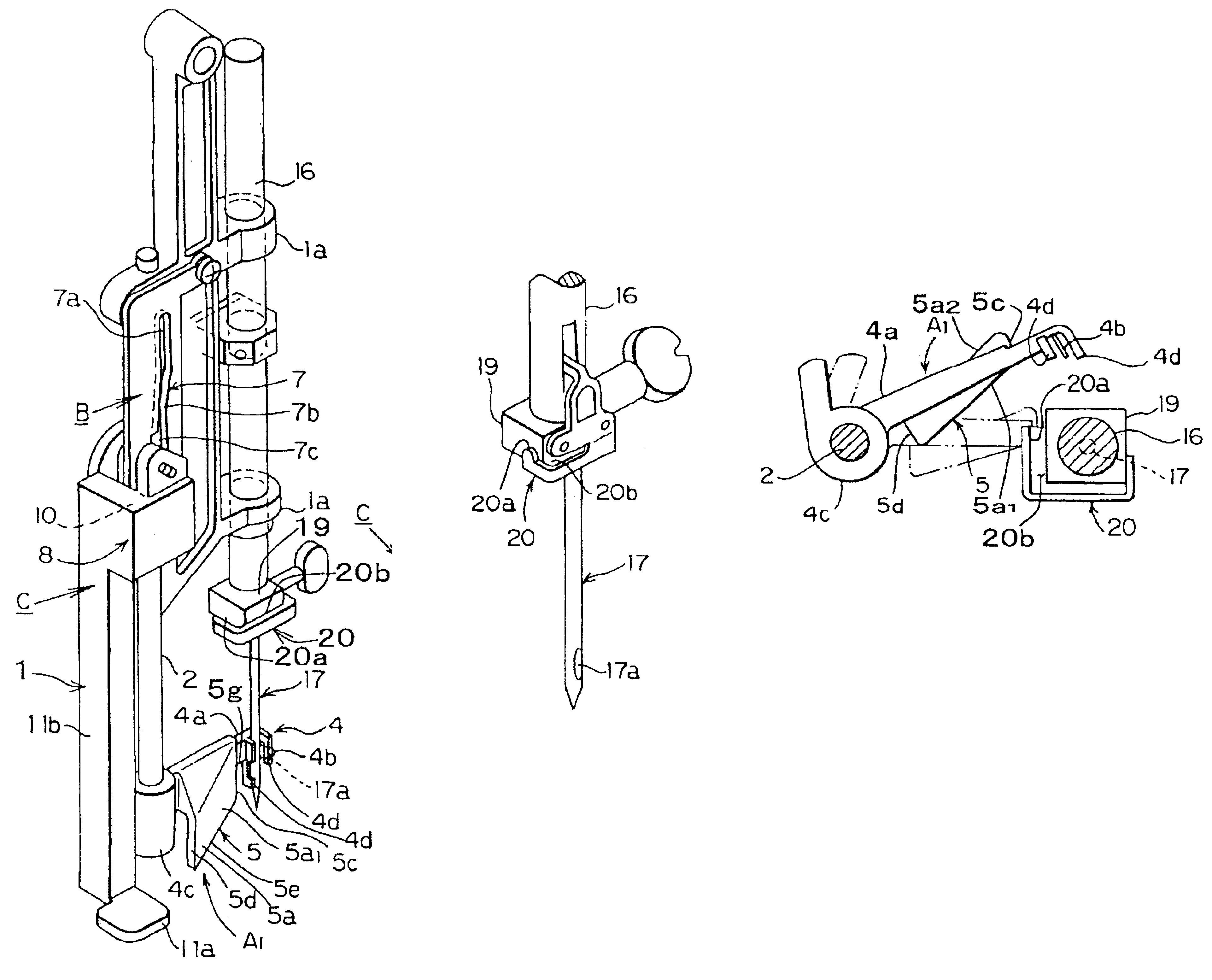
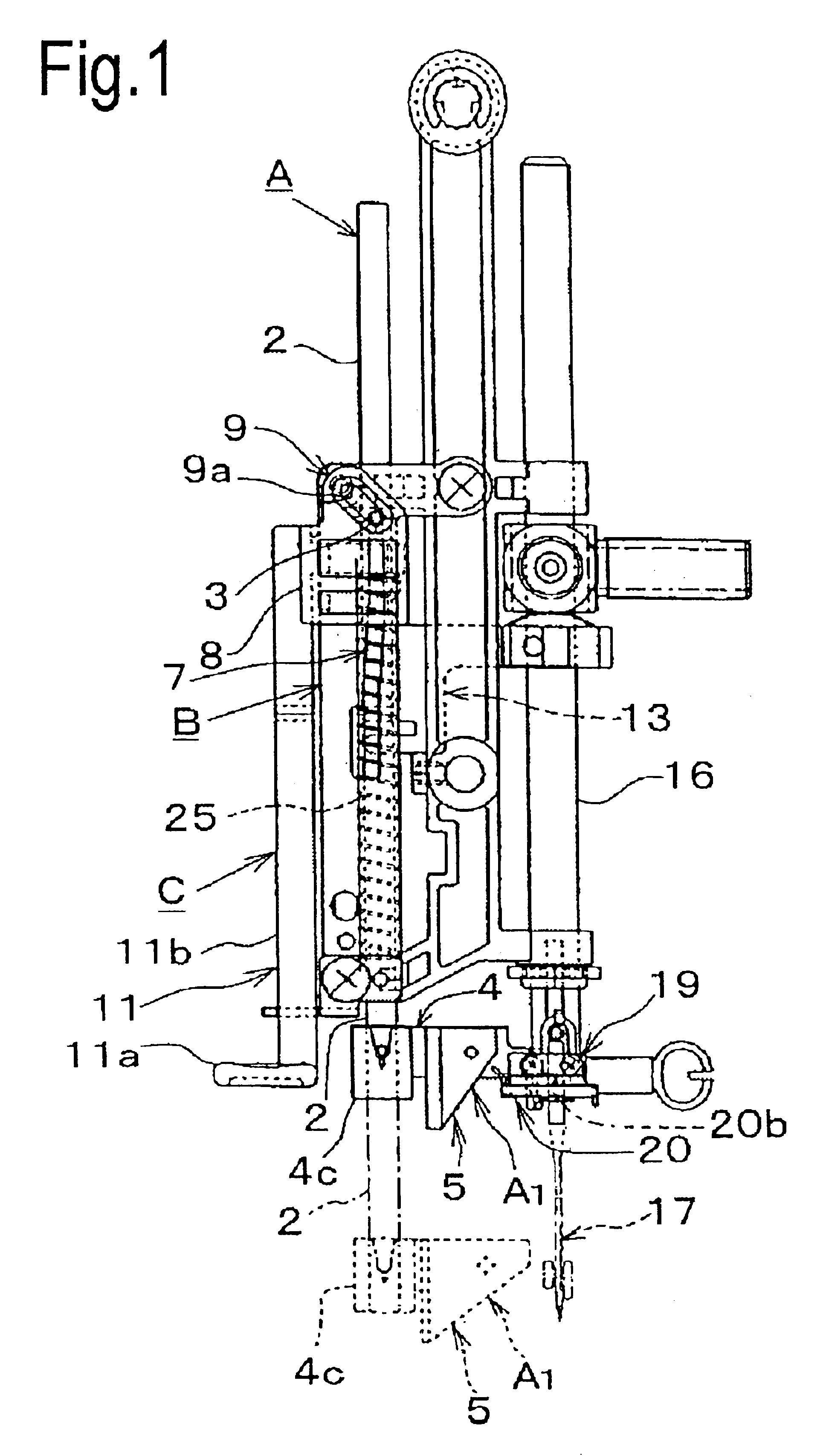
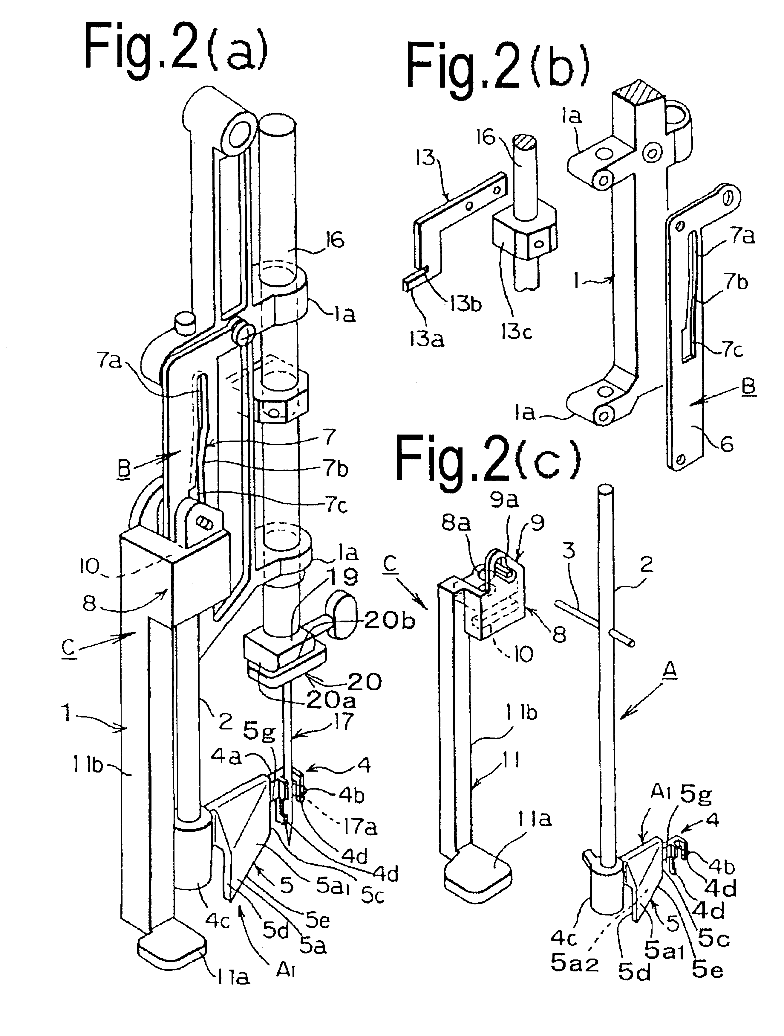
[0059]The invention will be described in reference to the embodiments as shown in the attached drawings. The invention is essentially composed of a threading shaft section A, a fixed guide section B and an operating section C as shown in FIGS. 1 and 2. These sections are mounted to a needle bar support 1. The needle bar support 1 is so structured as to support a needle bar 16 such that the same may be slidingly moved in vertical direction. The needle bar support 1 is mounted to a sewing machine such that the same may be swingingly movable across the direction in which a cloth is transported to be stitched. The needle bar support 1 is formed with upper and lower holder 1a, 1a for holding the needle bar 16 such that the same may be slidingly moved in vertical direction.

[0060]The needle bar 16 is provided with a thread holder 20 secured to the underside of a needle holder 19 of square block which is secured to the lower end of the needle bar 16. The thread holder 20 may be a plate whic...


PUM


Abstract

A threading device of sewing machine is disclosed, wherein the upper thread extended from a thread supply mounted on a sewing machine body may be easily and smoothly guided into engagement with a thread holder simultaneously when the threading device is operated to pass the upper thread through the eye of needle attached to the lower end of needle bar, the thread holder being arranged between the thread supply and the needle. The threading device comprises a vertically movable needle bar 16 having a needle attached to the lower end thereof, the needle having a needle eye, a needle bar support 1 for supporting the needle bar 16 such that the same may be vertically movable, a thread holder 20 mounted to the lower end of the needle bar 16, a threading member A1 having a thread engaging portion 5 and a threading hook 4b, a threading shaft 2 for having the threading member A1 secured to the lower end thereof, an operating section C for vertically moving and axially rotating the threading shaft 2 to pass the upper thread n through the needle eye 17a, the threading member A1 being so formed as to provide the thread engaging portion 5 for guiding the upper thread to the needle eye 17a, the needle holder 20 being formed with a groove 20b for holding the upper thread n, the groove 20b having an opening 20a at which the upper thread n is guided into the groove 20b from the rear side of the thread holder 20 while the thread engaging portion 5 is moved down with the upper thread n which is to be passed through the needle eye 17a.

Description

BACKGROUND OF THE INVENTION[0001]The present invention relates to a threading device of sewing machine, and more particularly relates to a threading device for guiding the upper thread smoothly and exactly into engagement with a thread holder while the threading device is operated to pass the upper thread through the needle eye of a machine needle, the upper thread being extended from a thread supply provided on the sewing machine and thread holder being provided to hold the upper thread between the thread supply and the machine needle.[0002]So far, many inventions have been made in connection with a threading device of sewing machine. According to the conventional threading device, a threading shaft is vertically moved down along a guide groove in association with downward movement of an operating member and is stopped at a place where there is a needle eye. With further movement of the operating member, the threading shaft is axially rotated.[0003]In association with the axial rot...

Claims


Application Information

Patent Timeline
Patent Type & Authority Patents(United States)
IPC IPC(8): D05B87/00D05B87/02
CPCD05B87/02
Inventor EBATA, YOSHIKAZUNAKAGAWA, TAMOTSUOMIYA, KOSHIRO
Owner JANOME CORP
Why Eureka
Try Eureka