Concentric bell assembly

Active Publication Date: 2005-07-19
DURR SYST INC
View PDF8 Cites 11 Cited by
  • Summary
  • Abstract
  • Description
  • Claims
  • Application Information

AI Technical Summary

Benefits of technology

[0008]When the second bell is disposed in the first bell position, a first bell depression surface disposed upon the first bell extends beyond the second bell so that the first bell depresses the tire being inflated. When the second bell is disposed in the second bell position, a second bell depression surface extends beyond t

Problems solved by technology

Providing a depression force to the second bell in this manner result in several drawbacks that could cause an inconsistent depression force upon a tire being inflated.
For example, dis

Method used


Image

  • Concentric bell assembly
  • Concentric bell assembly
  • Concentric bell assembly

Examples


Embodiment Construction

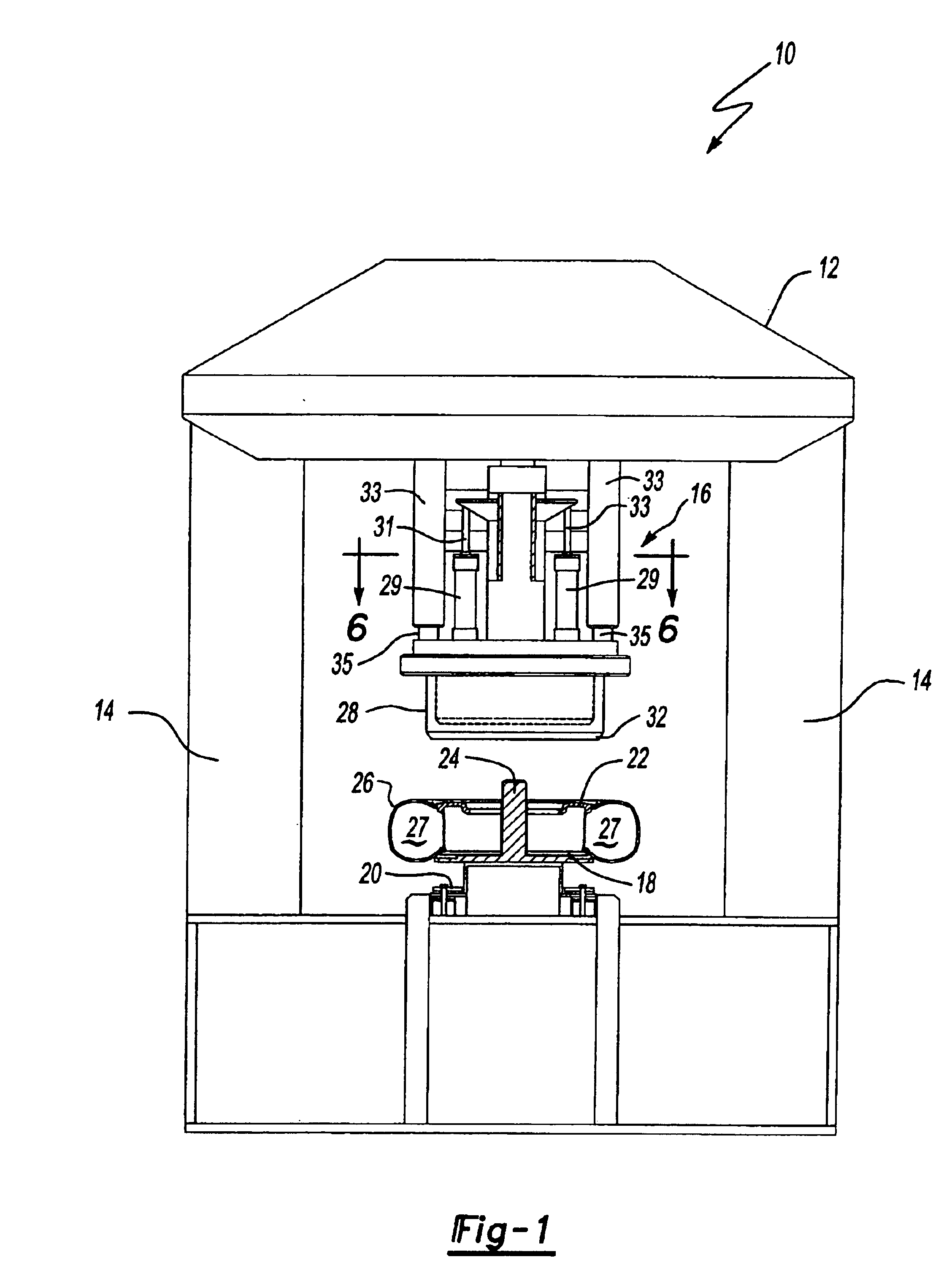
[0016]Referring to FIG. 1, an apparatus for inflating a tire is generally shown at 10. A frame 12 includes opposing support legs 14 and suspends a concentric bell assembly 16. A plurality of support trays 18 are moved sequentially beneath the bell assembly 16 by a conveyor 20 as is known to those of skill in the art. A wheel 22 is secured on the support tray 18 by a spindle 24 located to align the wheel along a common axis with the bell assembly 16 as will be explained further below. A tire 26 is previously mated to the wheel 22 in an uninflated state. The tire 26 is tubeless and forms a cavity 27 with the wheel 22.

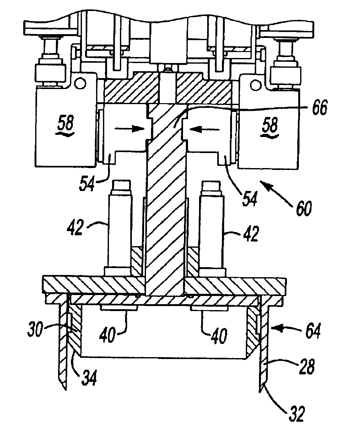
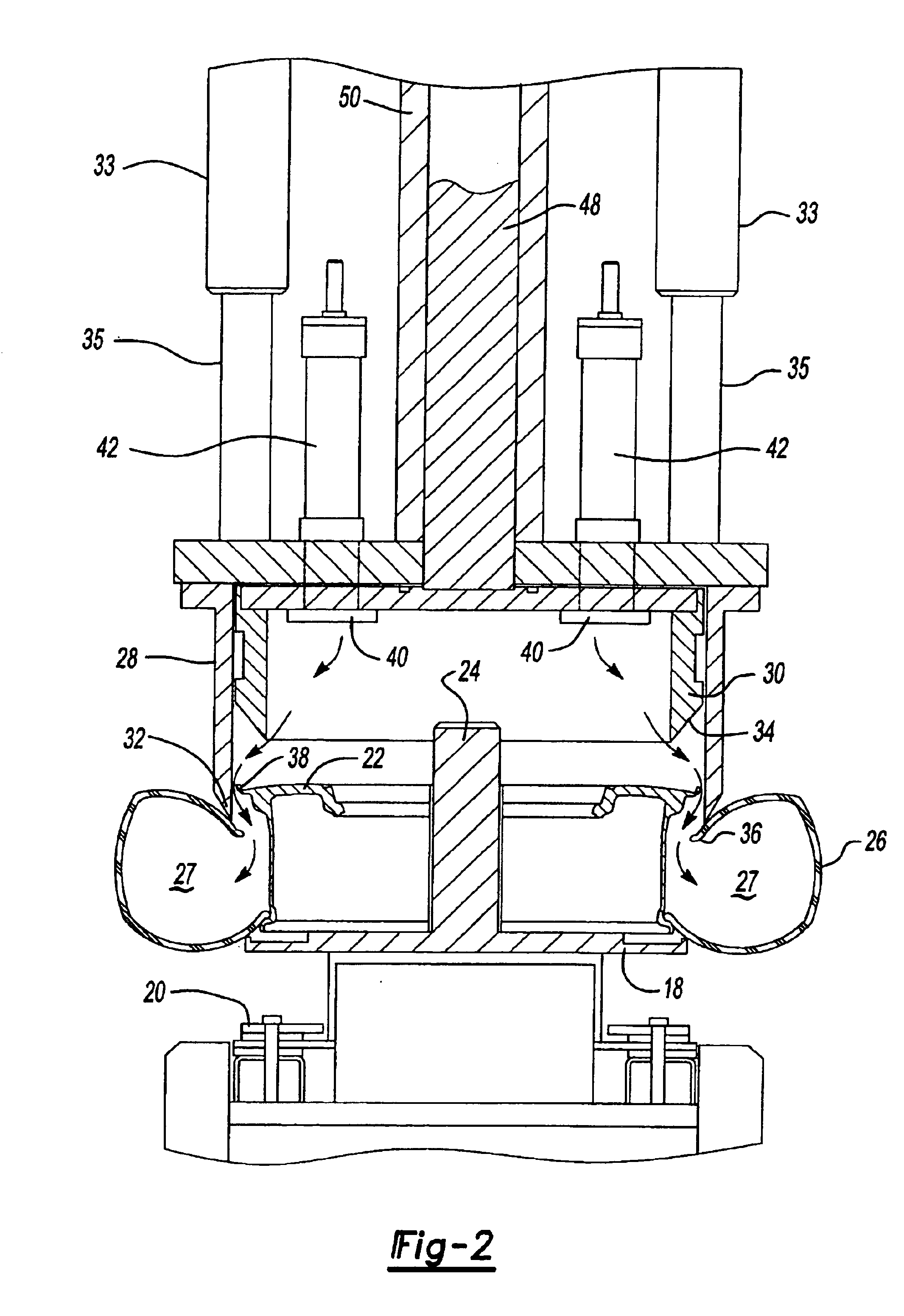
[0017]Referring to FIG. 2, the concentric bell assembly 16 is shown having a first bell 28 and a second bell 30 slidably disposed within the first bell 28. The second bell 30 has a smaller diameter than the first bell 28 and slides freely within the first bell 28.

[0018]The first bell 28 includes a first depression surface 32 and the second bell 30 includes a second depres...


PUM


Abstract

A bell assembly for inflating a tubeless tire on a wheel includes a first bell and a second bell slidably disposed within the first bell. The second bell includes a smaller diameter than the first bell. A shaft extends upwardly from the second bell in one of a relative to the first bell. A locking member is engagable with the shaft and is movable between a first locking position and a second locking position. The locking member secures the second bell in the first bell position when the locking member is disposed in the first locking position. The locking member secures the second bell in the second bell position when the locking member is disposed in the second locking position.

Description

PRIOR APPLICATIONS[0001]This Application claims priority to Provisional Application No. 60 / 419,237 filed Oct. 17, 2002.FIELD OF THE INVENTION[0002]The present invention relates generally toward a bell assembly for inflating a tubeless tire on a wheel. More specifically, the present invention relates to an improved concentric bell assembly used to inflate multiple tire sizes.BACKGROUND OF THE INVENTION[0003]Conventional wheel and tire assemblies used to support a motor vehicle include a tubeless tire having a bead that seals to a wheel flange in order to maintain a desirable air pressure between the tire and wheel. In mass production settings, it is necessary to inflate the tire rapidly in order to prevent a bottleneck in the assembly process. To rapidly inflate the tire, a bell, which circumscribes a wheel, is lowered to depress the tire separating the tire bead from the wheel flange. The bell forms a sealed enclosure with the tire interior enabling pressurized air to be injected th...

Claims


Application Information

Patent Timeline
IPC IPC(8): B60C25/00B60C25/14
CPCB60C25/00B60C25/145
Inventor PELLERIN, DANSINKE, CHAD A.TEPER, BORIS R.HOY, BRIAN
Owner DURR SYST INC
Why Eureka
Try Eureka