Supercharge Your Innovation With Domain-Expert AI Agents!

Fuel-injection valve

a technology of fuel injection valve and fuel injector, which is applied in the direction of fuel injector pumps, machines/engines, mechanical equipment, etc., can solve the problems of negative effect on the operation of fuel injectors and gaps, and achieve the effects of less sensitive to manufacturing tolerances, easy manufacturing, and elimination of throttle effects

Inactive Publication Date: 2005-07-19
ROBERT BOSCH GMBH
View PDF14 Cites 6 Cited by
  • Summary
  • Abstract
  • Description
  • Claims
  • Application Information

AI Technical Summary

Benefits of technology

The present invention provides a fuel injector with a valve seat element that has a ring-shaped elevation on its end face, which reduces gaps between the valve seat element and the swirl element during assembly and operation. The ring-shaped elevation compensates for any unevenness in the surfaces of the valve seat element and swirl element caused by manufacturing processes. The design of the ring surface makes the component part less sensitive to manufacturing tolerances. The swirl element is clamped in between the guide element and the valve seat element during assembly, so temperature changes during operation have no effect on the gap width or the quantity of metered fuel. The fuel channels of the guide element are advantageously arranged so that fuel may run without hindrance and without disturbing throttle effects into the swirl channels and flow to the sealing seat. The design of a swirl chamber is also of advantage, whose volume is selected, depending on the requirements, so throttle effects may be eliminated. The wedge-shaped areas at the end face of the valve seat element, bordering on the ring-shaped elevation, are easy to manufacture and, depending on the requirements, may be provided with any angles relative to a horizontal plane of reference. The ring-shaped elevation may also be made in the shape of a ring which is attached to the end face of the valve seat element.

Problems solved by technology

It is particularly disadvantageous in the fuel injector known from the above-named document that gaps are created, during assembly of the swirl element, between the swirl element and the guide element, as well as between the swirl element and the valve seat element.
This has a negative effect on the operation of the fuel injector because of differences in the metered fuel quantity per injection cycle.

Method used


Image

  • Fuel-injection valve
  • Fuel-injection valve
  • Fuel-injection valve

Examples


Embodiment Construction

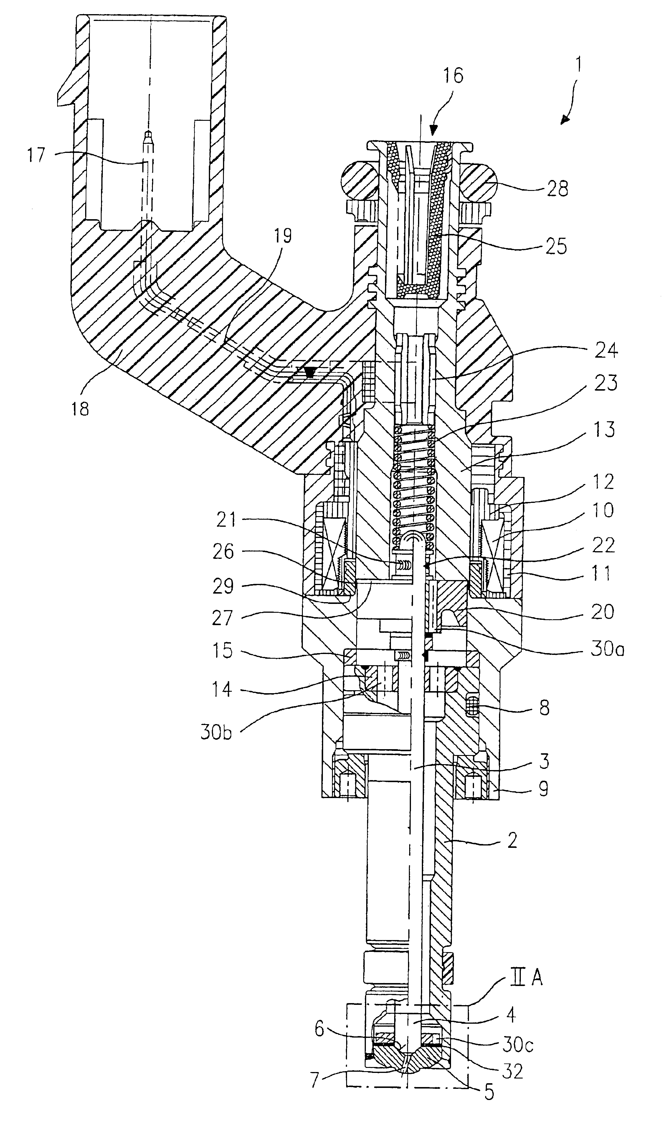
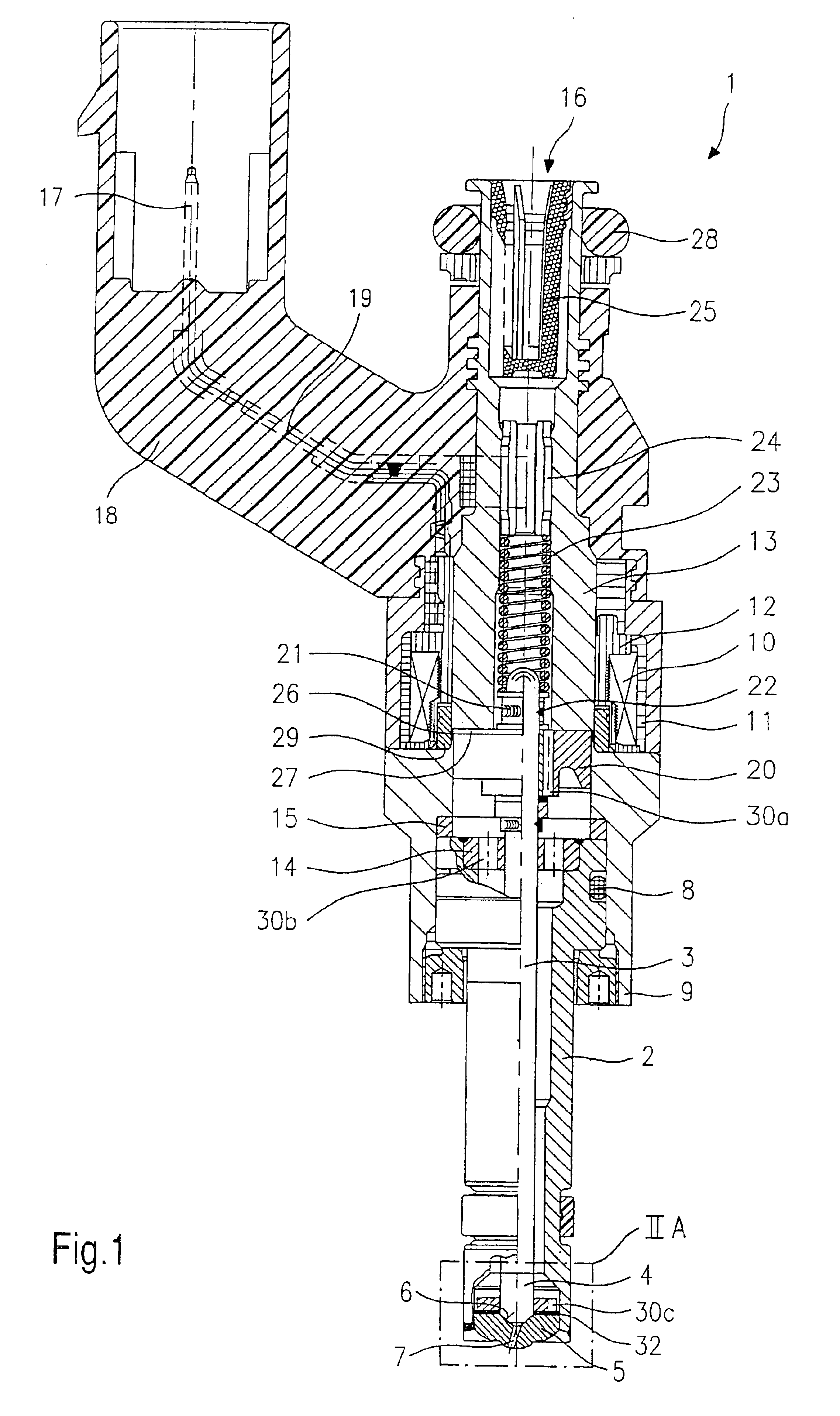
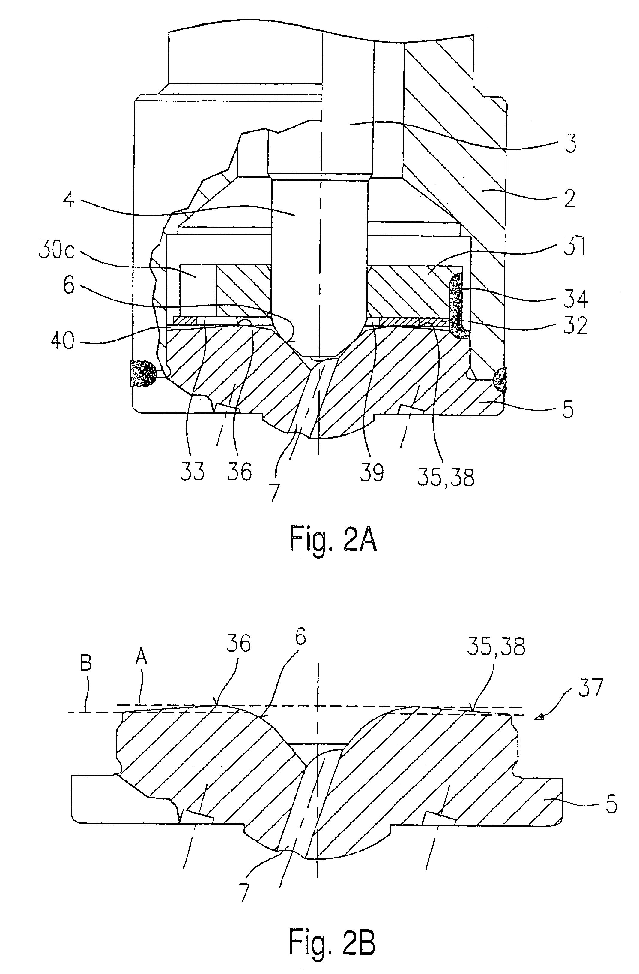
[0017]Before exemplary embodiments of a fuel injector according to the present invention are described more precisely with reference to FIGS. 2A through 2D, to understand the invention better, fuel injector 1 shall first of all be briefly explained in an overall representation with respect to its important components with the aid of FIG. 1.

[0018]Fuel injector 1 is designed in the form of an injector for fuel-injection systems of mixture-compressing internal combustion engines having externally supplied ignition. Fuel injector 1 is particularly suitable for directly injecting fuel into a combustion chamber (not illustrated) of an internal combustion engine.

[0019]Fuel injector 1 includes a nozzle body 2, in which a valve needle 3 is positioned. Valve needle 3 is connected in operative connection to a valve-closure member 4 that cooperates with a valve-seat surface 6, arranged on a valve-seat member 5, to form a sealing seat. Fuel injector 1 in the exemplary embodiment is an inwardly o...


PUM


Abstract

A fuel injector, especially for the direct injection of fuel into a combustion chamber of an internal combustion engine has an actuator which is in operative connection with a valve needle, the valve needle having a valve-closure member at its spray-off end, which cooperates to form a sealing seat together with a valve seat surface which is formed on a valve seat element. Valve-closure member reaches through a swirl element which is positioned on a flow-supply side end face of valve seat element, swirl channels being formed in swirl element. The valve seat element has a ring-shaped elevation on the flow-supply side end face facing the swirl element.

Description

FIELD OF THE INVENTION[0001]The present invention relates to a fuel injector.BACKGROUND INFORMATION[0002]A fuel injector is described in German Published Patent Application No. 197 36 682 for direct injection of fuel into the combustion chamber of a mixture-compressing, internal combustion engine having externally supplied ignition, which has a guide and seating region at the downstream end of the fuel injector formed by three disk-shaped elements. In this connection, a swirl element is embedded between a guide element and a valve seat element. The guide element is used for guiding an axially movable valve needle reaching through it, while a valve closing section of the valve needle acts together with a valve seat surface of the valve seat element. The swirl element has an inner opening region having several swirl channels which are not in communication with the outer circumference of the swirl element. The entire opening region extends completely over the axial thickness of the swi...

Claims


Application Information

Patent Timeline
Patent Type & Authority Patents(United States)
IPC IPC(8): F02M61/00F02M61/16F02M61/18F02M51/06F02B75/12F02B75/00F02M51/08F02M61/10
CPCF02M51/0671F02M61/162F02M61/168F02M61/18F02B2075/125Y02T10/123Y02T10/12
Inventor LUFT, HEINZ
Owner ROBERT BOSCH GMBH
Features
  • R&D
  • Intellectual Property
  • Life Sciences
  • Materials
  • Tech Scout
  • Unparalleled Data Quality
  • Higher Quality Content
  • 60% Fewer Hallucinations
Learn More