Shaft/hub connection

Inactive Publication Date: 2005-07-19
ABB TURBO SYST
View PDF8 Cites 19 Cited by
  • Summary
  • Abstract
  • Description
  • Claims
  • Application Information

AI Technical Summary

Benefits of technology

[0011]Owing to the small angle between the load-bearing flanks, bearing frictionally on one another with their large surfaces, and the axis, the radial pressure decisive for the torque transmission is correspondingly greater than in conventional

Problems solved by technology

In addition, a further restriction is the notch effect caused in conventi

Method used


Image

  • Shaft/hub connection
  • Shaft/hub connection
  • Shaft/hub connection

Examples


Example

WAY OF IMPLEMENTING THE INVENTION

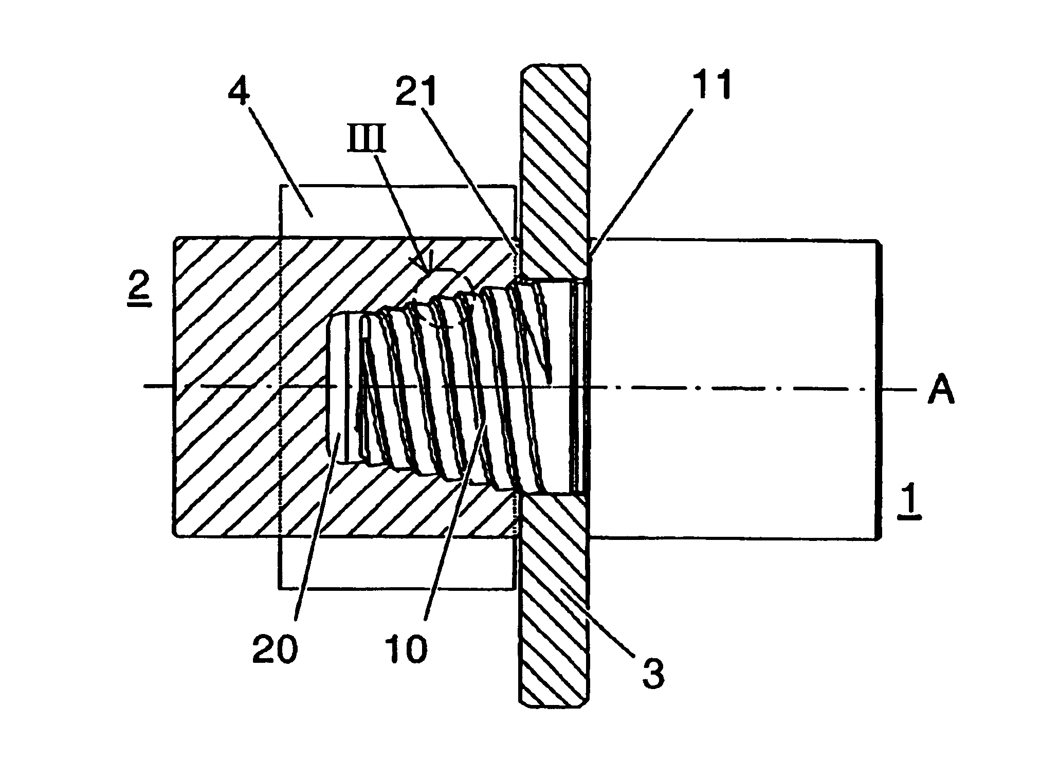
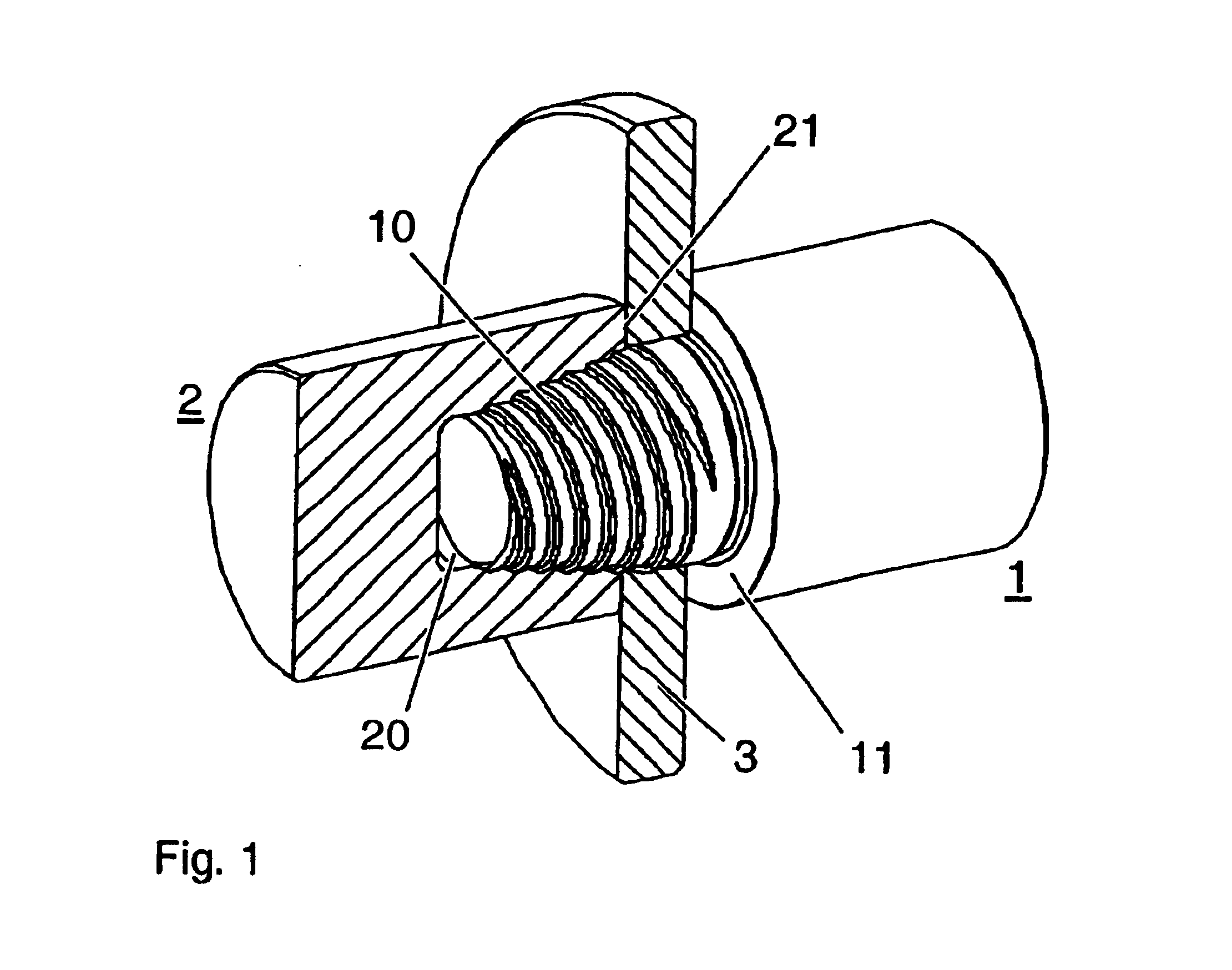
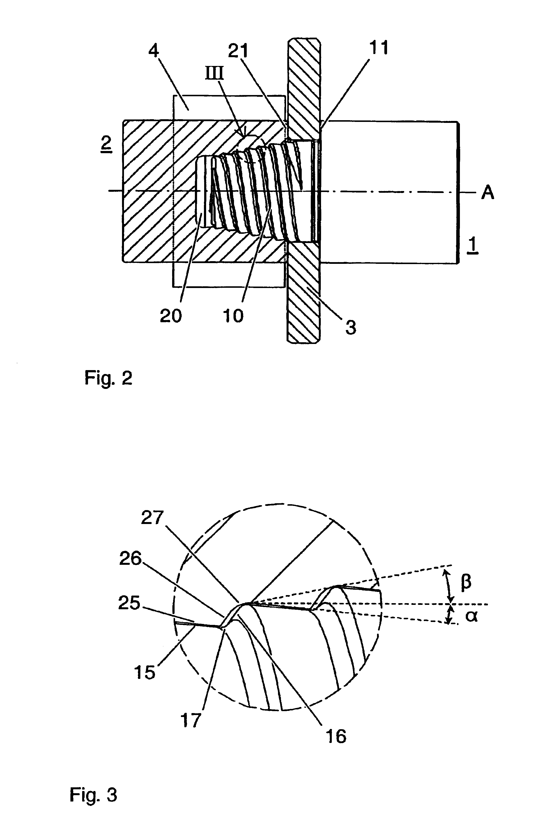
[0022]FIG. 1 shows a shaft 1 and a shaft attachment 2 connected according to the invention to the shaft. By way of example, the shaft attachment is depicted as a cylindrical counterpart corresponding approximately to the shaft in shape and size. As a rule, the shaft attachment is a wheel-shaped part, such as, for instance, the compressor wheel of a turbocharger.

[0023]The shaft has an external thread in the region of the connecting point. In the embodiment shown, the external thread is formed on the shaft end in the form of a threaded stem 10. A corresponding bore 20 which is provided with an internal thread is incorporated in the shaft attachment.

[0024]For the axial positioning of the shaft attachment relative to the shaft, the shaft and shaft attachment have an axial stop 11 and 21. As a rule, the two axial stops have surfaces which are produced with high precision and are parallel to one another, whereby they contribute substantially to the concent...


PUM


Abstract

The shaft is connected to the shaft attachment by a thread. A bore with an internal thread is incorporated in the shaft attachment and the shaft has a corresponding stem which can be introduced into the threaded bore and has an external thread. An axial stop is arranged on the shaft and on the shaft attachment. The internal and external threads have torque-transmitting flanks which are flat toward the axis and which can be connected to one another frictionally by radial pressure by mutual rotation of shaft and shaft attachment with interaction between the axial stops. Owing to the small angle between the load-bearing flanks and the axis, the radial pressure decisive for the torque transmission is correspondingly greater than in conventional threaded connections. As a result, the axial prestressing force between the two parts to be connected can be correspondingly reduced.

Description

TECHNICAL FIELD[0001]The invention relates to the field of shaft / hub connections.[0002]It relates to the connection of a shaft to a shaft attachment by means of a thread according to the preamble of patent claim 1. It also relates to a turbocharger, the turbine shaft of which is correspondingly connected to the compressor wheel.PRIOR ART[0003]Turbochargers for increasing the output of reciprocating piston engines comprise a turbine driven by engine exhaust gases and a compressor connected to the turbine via a torque-transmitting shaft. Turbochargers for lower engine outputs advantageously have a radial compressor of aluminum without a continuous central bore, as disclosed, for instance, by DE 44 44 082.[0004]In this case, for production and maintenance reasons, the compressor wheel is releasably connected to the turbine shaft.[0005]In the known solutions, the compressor wheel is screwed onto a shaft stub with a conventional thread either directly or via an intermediate bush of steel...

Claims


Application Information

Patent Timeline
IPC IPC(8): F01D5/02
CPCF01D5/025F05D2250/232Y10T403/56F05D2220/40F05D2250/281
Inventor BATTIG, JOSEFMULLER, ALFREDFLURY, BALZ
Owner ABB TURBO SYST
Why Eureka
Try Eureka