
Disposable injection device

a single-use injection and injection device technology, applied in the direction of intravenous devices, ampoule syringes, infusion needles, etc., can solve the problems of increased production costs on an industrial scale which are relatively low in comparison with the production cost of a conventional pre-filled syringe without protection, and the injection device of this type does not provide absolute safety for its user

Inactive Publication Date: 2005-07-19
SANOFI SA
View PDF17 Cites 68 Cited by
  • Summary
  • Abstract
  • Description
  • Claims
  • Application Information

AI Technical Summary

Benefits of technology

[0013]The object of the present invention is to eliminate all the above-described disadvantages of the techniques for protection after use of the injection devices, and its main objective is to provide an injection device which leads to the fluid being administered in accordance with a natural gesture, and which guarantees total injection of the dose of fluid.
[0028]According to this embodiment the syringe / syringe body assembly is retracted inside the protective case, firstly after axial displacement of the locking ring, and secondly when the user ceases to exert pressure on the thruster of the plunger rod. Consequently, the triggering takes place gently, without any jolting for the patient.
[0038]Advantageously, the locking ring also comprises a rear tubular section, which is designed to surround the rear inner rib of the protective case, such as to shrink the latter on, and to prevent any risk of escape of the tubular ring.

Problems solved by technology

However, it has been found that a design of this type has a major disadvantage, derived from the fact that, when the cap is replaced on the needle, the cap must be presented opposite the end of this needle.
In fact, this requirement has proved to be the cause of relatively frequent accidents, by being pricked, with all the risks which this pricking with a contaminated needle involves.
In addition, syringes of this type have no safety device which is designed to prevent them from being re-used, and particular care must therefore be taken in order to destroy them.
This first solution leads to the production of injection devices with a simple design, such as those described in patent FR 2,733,687, which involve an additional production cost on an industrial scale which is relatively low in comparison with the production cost of a conventional pre-filled syringe without protection.
On the other hand, injection devices of this type do not provide absolute safety for their user in relation to the risk of being pricked.
Consequently, and more particularly in the case of injection devices with small dimensions which are designed for injection of small doses of fluid, any sliding of the fingers on the protective case can lead the user to prick himself with the injection needle.
However, injection devices of this type have a major disadvantage derived from the fact that, during triggering of the resilient means, which is controlled by unlocking means which are disposed on the plunger rod, it is in no way guaranteed that the syringe has been completely emptied, owing to the tolerances accepted concerning the length of syringes during manufacture of the latter.
Since injection devices of this type are designed in particular to be used for injection of very small doses of fluids (of approximately a cubic millimeter), the quantity administered of which must be rigorously respected, this technical solution is unsuitable for fulfilling the requirements which apply.
It has been found however, that injection devices of this type, which require specific action other than the natural gesture used for the injection, have been badly received by medical personnel and by patients who administer their own medication, and in fact are very little used.
However, this solution has also encountered a negative response from medical personnel and the patients, and is not highly valued at present.

Method used


Image

  • Disposable injection device
  • Disposable injection device
  • Disposable injection device

Examples


Embodiment Construction

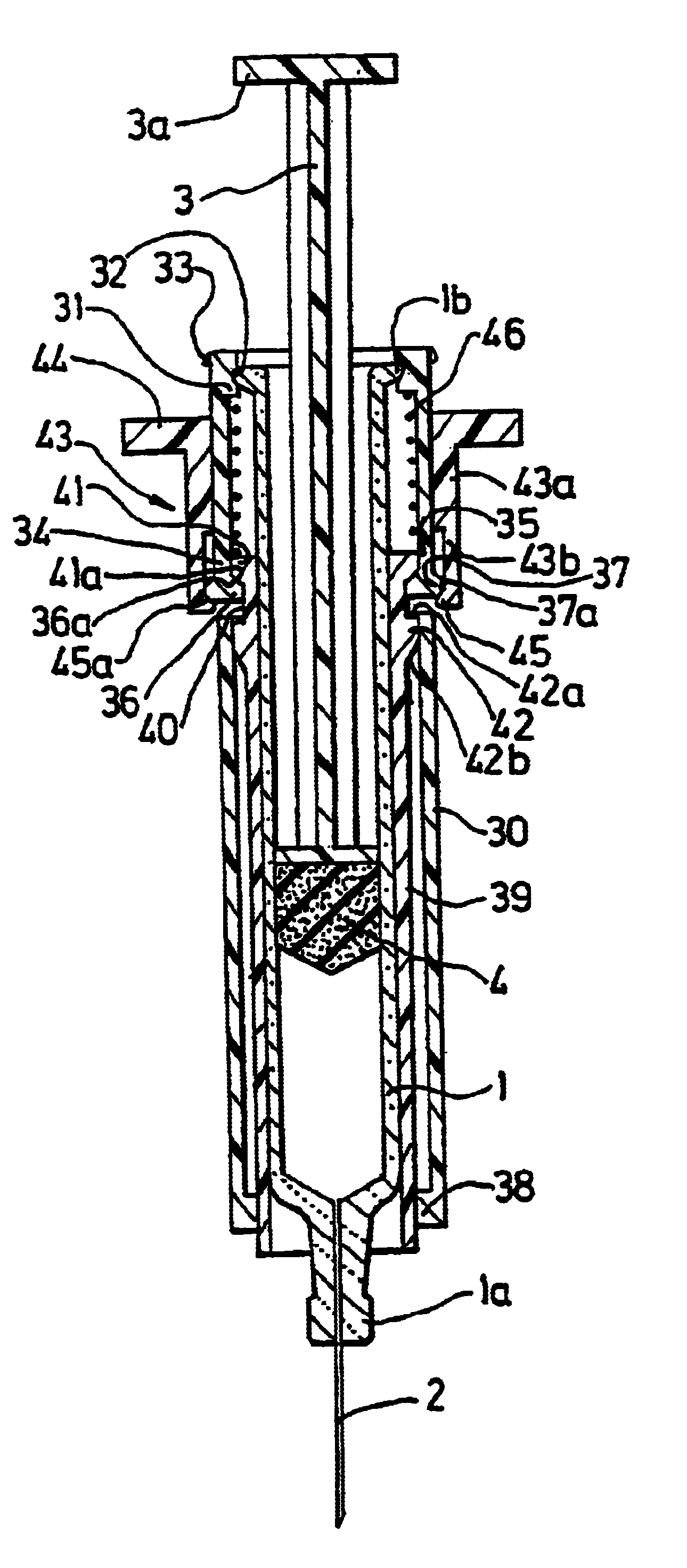
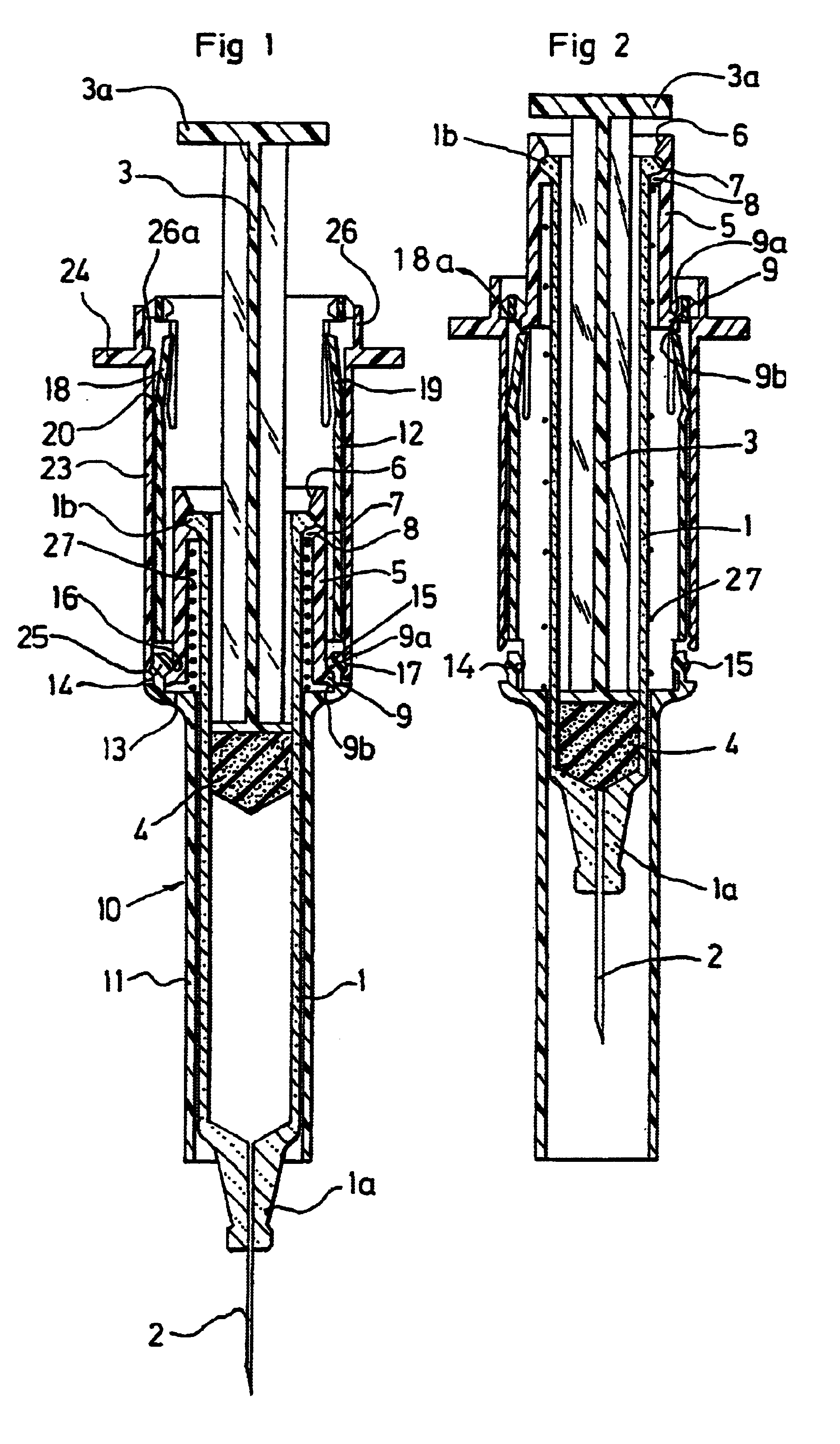
[0061]The injection devices according to the invention, represented respectively in FIGS. 1, 2 and 7, 8, both comprise firstly a pre-filled syringe 1 of a conventional type, which for example is made of glass, comprising in a conventional manner a front nose 1a, on which there is, fitted a needle 2, and a collar 1b at the level of its rear end.

[0062]This syringe 1 also comprises in a conventional manner a plunger rod 3, which is provided with a thruster 3a at the level of its rear end, and activates a plunger 4 which is integral with its front end.

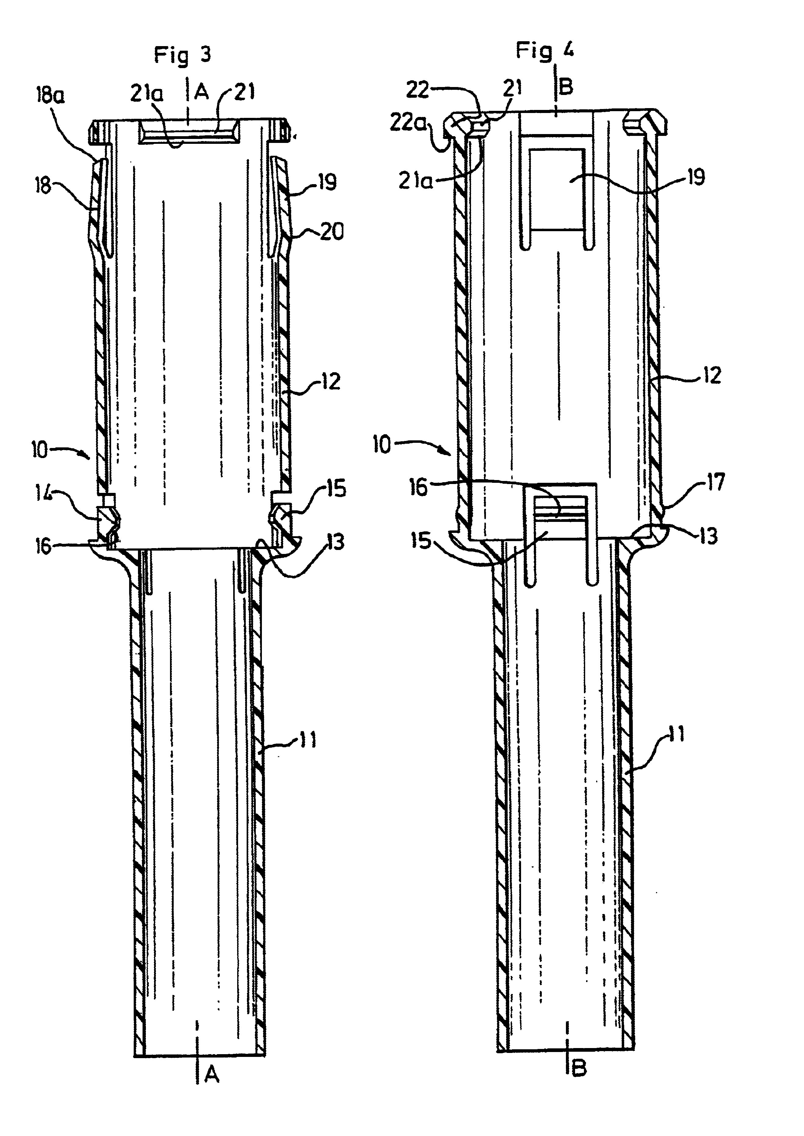
[0063]The injection device represented in FIGS. 1 and 2 additionally comprises a syringe body, which is designed to be rendered integral with the syringe 1, and consists of a tubular ring 5, which is represented in detail in FIG. 5.

[0064]This tubular ring 5 comprises firstly a rear end portion 6 with a frusto-conical shape, forming a ramp which allows it to pass over the collar 1b of the syringe 1, and, juxtaposed with the said frusto-coni...


PUM


Abstract

A single-use injection device, includes a pre-filled syringe (1), a syringe body (5) which is integral with the said syringe, and a protective case (10), the syringe body and protective case being provided with elements (9, 14, 15, 21) for relative locking in translation, which permit their relative displacement between a position of injection and a position of protection after use. The injection device includes a locking ring (23), which is provided with digital support elements (24), and locking units (25), which can lock the syringe body (5) and the protective case (10), in their position of injection, during injection, and can be displaced axially, such as to permit relative displacement of the syringe body and protective case, towards their position of protection after use, under the effect of the action of resilient member (27), only when the plunger (4) has reached its end of travel.

Description

BACKGROUND OF THE INVENTION[0001]The invention relates to a single-use injection device, which is designed to be pre-filled with a dose of fluid to be injected.DESCRIPTION OF THE RELATED ART[0002]The single-use injection devices which are conventionally used at present consist of pre-filled syringes which are provided with a cap, which is designed to protect the needle before use, then is removed for the purpose of the injection, and is finally put back into place after the injection has been carried out, in order to prevent subsequent risks of being pricked by the contaminated needle.[0003]However, it has been found that a design of this type has a major disadvantage, derived from the fact that, when the cap is replaced on the needle, the cap must be presented opposite the end of this needle. In fact, this requirement has proved to be the cause of relatively frequent accidents, by being pricked, with all the risks which this pricking with a contaminated needle involves. In addition...

Claims


Application Information

Patent Timeline
IPC IPC(8): A61M5/32A61M5/28A61M5/31
CPCA61M5/326A61M2005/3247A61M2005/3261
Inventor BRUNEL
Owner SANOFI SA
Learn More