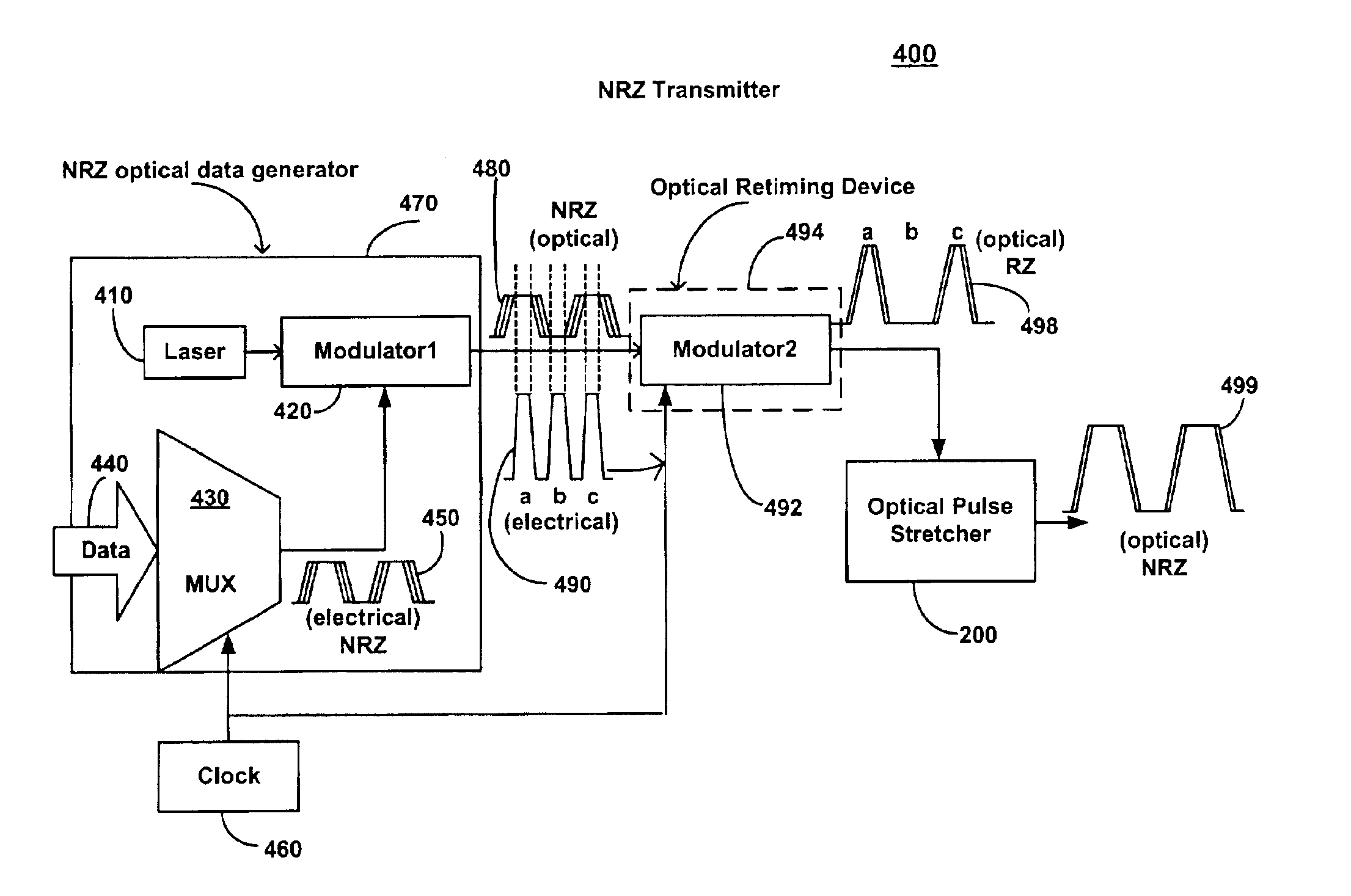
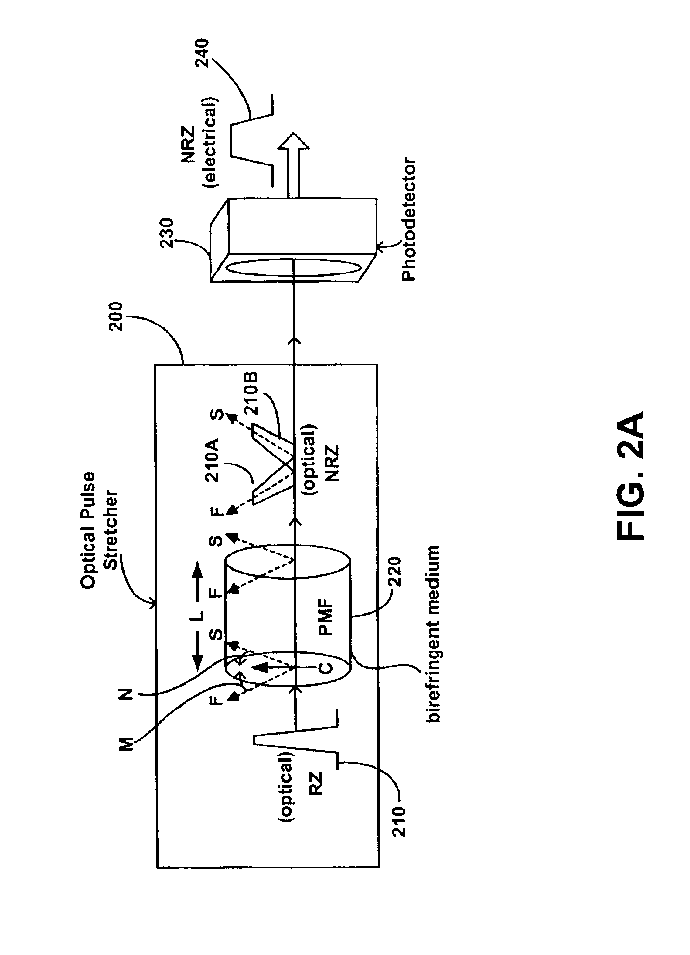
Optical pulse stretcher for converting RZ optical data to NRZ optical data for a low jitter NRZ transmitter
a technology of optical data and optical pulse, which is applied in the field of optical pulse stretchers, can solve the problems of significant distortion of the shape of the stretched optical pulse, interference (destructive or constructive) between the combining pulse portions, and the impairment of optical data transmission, so as to reduce the jitter of optical data and achieve low jitter optical data
- Summary
- Abstract
- Description
- Claims
- Application Information
AI Technical Summary
Benefits of technology
Problems solved by technology
Method used
Image

Examples
Embodiment Construction
[0018]Reference will now be made in detail to embodiments of the present invention, examples of which are illustrated in the accompanying drawings. While the invention will be described in conjunction with these embodiments, it will be understood that they are not intended to limit the invention to these embodiments. On the contrary, the invention is intended to cover alternatives, modifications and equivalents, which may be included within the spirit and scope of the invention as defined by the appended claims. Furthermore, in the following detailed description of the present invention, numerous specific details are set forth in order to provide a thorough understanding of the present invention.
[0019]In the description of the present invention, it should be understood that “optical” applies to any form of electromagnetic signal (e.g., radio frequency, microwave, millimeter wave, infrared, visible, ultraviolet, x-ray, etc.) irrespective of the medium of propagation (e.g., free space...
PUM
| Property | Measurement | Unit |
|---|---|---|
| angle | aaaaa | aaaaa |
| angles | aaaaa | aaaaa |
| optical data | aaaaa | aaaaa |
Abstract
Description
Claims
Application Information
 - R&D
- Intellectual Property
- Life Sciences
- Materials
- Tech Scout
- Unparalleled Data Quality
- Higher Quality Content
- 60% Fewer Hallucinations
Browse by: Latest US Patents, China's latest patents, Technical Efficacy Thesaurus, Application Domain, Technology Topic, Popular Technical Reports.
© 2025 PatSnap. All rights reserved.Legal|Privacy policy|Modern Slavery Act Transparency Statement|Sitemap|About US| Contact US: help@patsnap.com