Bare stent ship and crimp device

Inactive Publication Date: 2005-07-26
BOSTON SCI SCIMED INC
View PDF14 Cites 45 Cited by
  • Summary
  • Abstract
  • Description
  • Claims
  • Application Information

AI Technical Summary

Benefits of technology

[0014]The bars of the stent containers disclosed above are desirably spaced apart such that the stent is visible between adjacent bars to facilitate positioning t

Problems solved by technology

It can also affect the dilatation length of t

Method used


Image

  • Bare stent ship and crimp device
  • Bare stent ship and crimp device
  • Bare stent ship and crimp device

Examples


Example

[0035]While this invention may be embodied in many different forms, there are described in detail herein specific preferred embodiments of the invention. This description is an exemplification of the principles of the invention and is not intended to limit the invention to the particular embodiments illustrated.

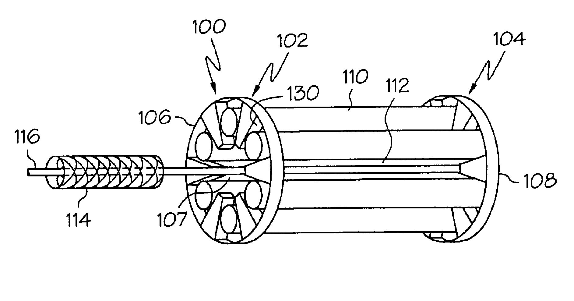
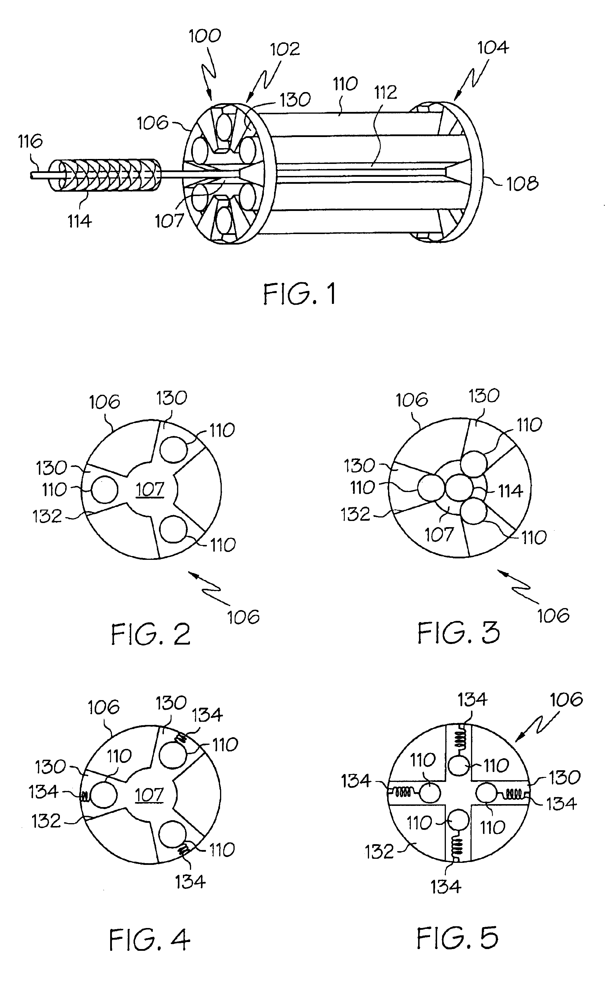
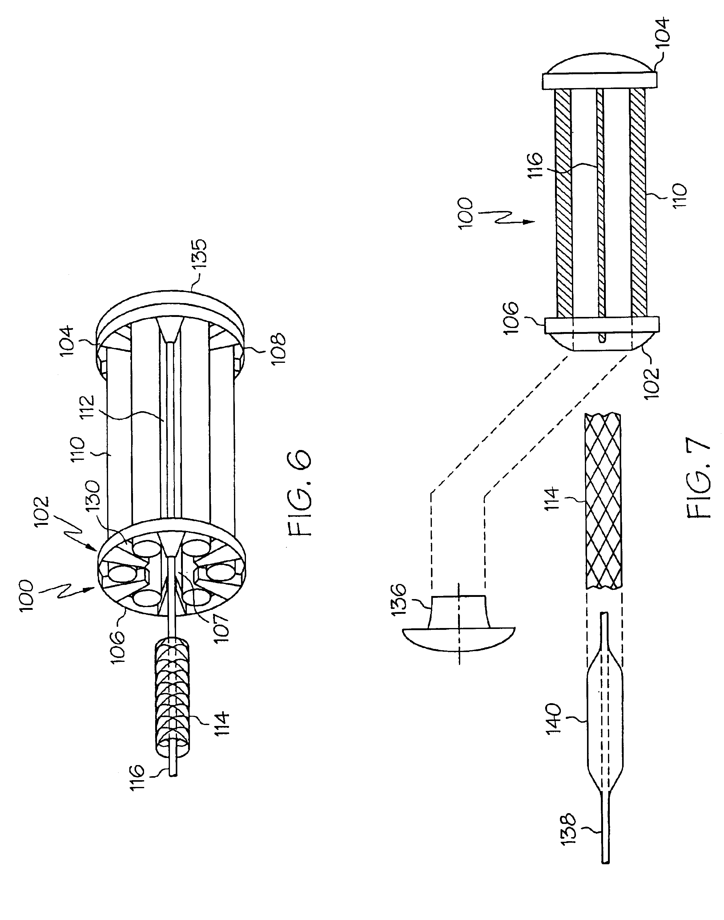
[0036]For the purposes of this disclosure, unless otherwise indicated, like reference numerals in the figures refer to the same component. Also for the purposes of this disclosure, the term ‘stent’ shall refer to stents, grafts and stent-grafts. Finally, for the purposes of this disclosure, any references made to reducing a stent in size refer to a reduction in the transverse cross-section of the flowpath through the stent.

[0037]The instant invention, in one or more of its embodiments, is directed to devices which may be used to reduce stents in size and / or to store and ship stents. The devices may be used to reduce stents in size prior as a precursor to crimping the stent or...


PUM

PropertyMeasurementUnit
Timeaaaaaaaaaa
Timeaaaaaaaaaa
Timeaaaaaaaaaa

Abstract

A stent container has a first wall at the proximal end and a second wall at the distal end. The first wall has an opening therethrough sized for receiving an uncrimped stent therethrough. The opening opens into a chamber which is reducible in size from a first enlarged size to a second reduced size. The chamber in the first enlarged size is sized for receiving an uncrimped stent therein. A plurality of bars extend from the first wall to the second wall. The bars are movable between a first position and a second position. The plurality of bars in the first position and the first and second walls define the periphery of the chamber in the enlarged size. The plurality of bars in the second position and the first and second walls define the periphery of the chamber in the reduced size. A stent disposed in the chamber may be reduced in size by reducing the chamber from the first enlarged size to the second reduced size.

Description

CROSS REFERENCE TO RELATED APPLICATIONS[0001]This is a continuation of U.S. patent application Ser. No. 09 / 681,009 filed Nov. 16, 2000 which is incorporated by reference herein in its entirety.BACKGROUND OF THE INVENTION[0002]A stent is a generally tubular device that is used to support a bodily lumen.[0003]A stent is typically delivered to a desired bodily location via a catheter. In the case of a mechanically expandable stent such as a balloon expandable stent, the stent is disposed about the balloon and crimped to the balloon to prevent undesired movement of the stent relative to the balloon.[0004]A number of techniques for crimping a stent to a balloon are used. One such technique that is commonly used in the radiological suite involves hand crimping the stent to the balloon. A stent is placed over an uninflated balloon and then squeezed with the fingers until the stent is in intimate contact with the uninflated balloon. The technique is highly operator dependent and can affect ...

Claims


Application Information

Patent Timeline
IPC IPC(8): A61F2/06B21D39/04B25B27/14A61F2/84A61M25/12
CPCA61F2/958B21D39/048B25B27/146A61F2002/9522Y10T29/53991Y10T29/53987Y10T29/53657Y10T29/53909A61F2/9522
Inventor THORNTON, SALLY C.
Owner BOSTON SCI SCIMED INC
Why Eureka
Try Eureka