
Wall panel arrangement with accessory-supporting top cap

a top cap and wall panel technology, applied in shaft equipment, couplings, manufacturing tools, etc., can solve the problems of limited flexibility in arranging a workstation and load-bearing capability, inability to interiorly accommodate electrical components and cabling for providing power and/or communication capabilities to the workstation, and restrictions on the configuration of the workstation,

Inactive Publication Date: 2005-07-26
HAWORTH SPA
View PDF35 Cites 63 Cited by
  • Summary
  • Abstract
  • Description
  • Claims
  • Application Information

AI Technical Summary

Benefits of technology

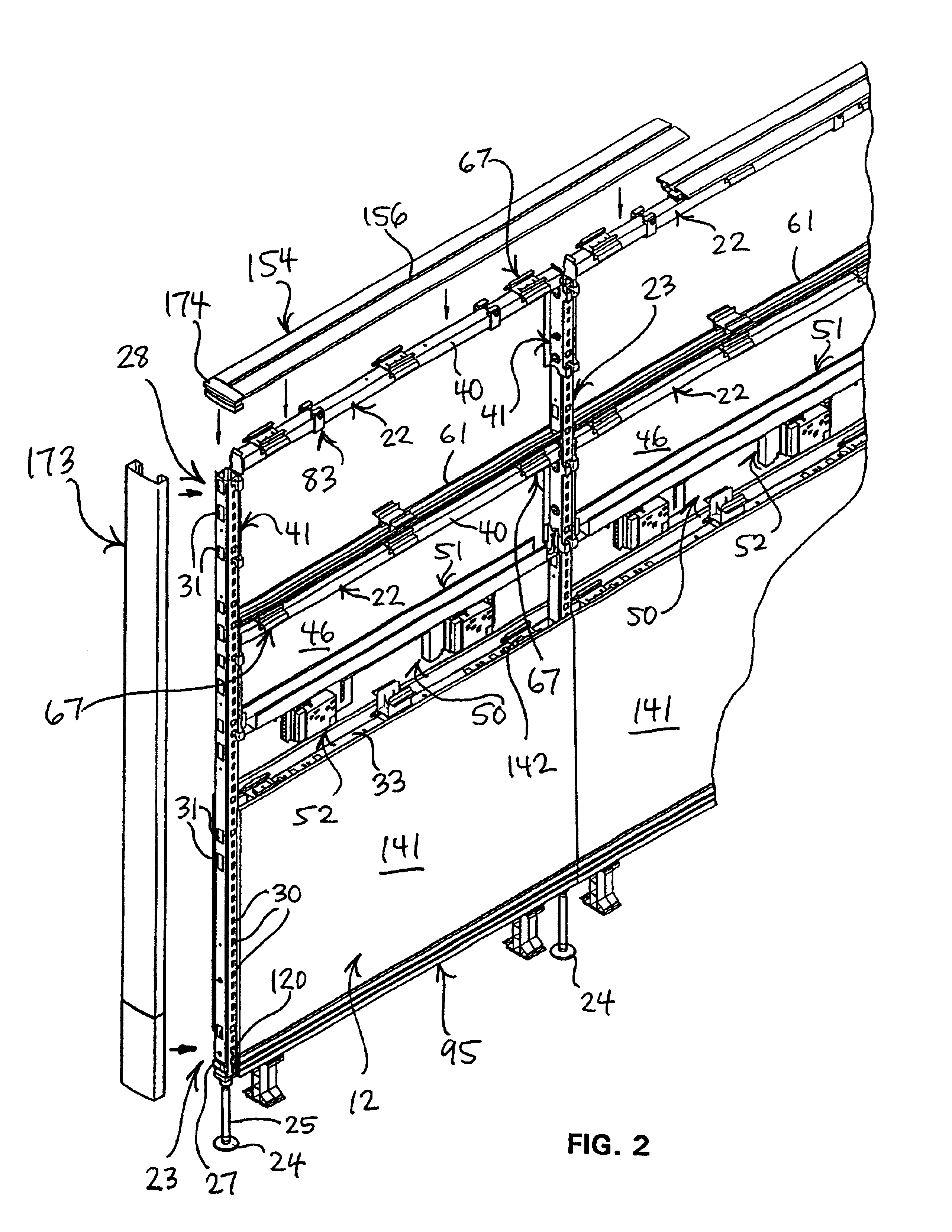
[0009]The top cap member according to the invention is of a rigid construction, and is supported on and clamped to the uppermost cross rail of a panel assembly. Further, the accessory-mounting brackets cooperate with the top cap member, and are also engaged with a lower frame component. This arrangement provides significant load-bearing capabilities, so as to permit mounting of shelving and the like. In addition, the top cap member can be utilized to mount a support post in a position intermediate the opposite vertical side edges of a respective panel assembly. A wall panel or return wall can then be mounted to the intermediate support post so as to create a T-shaped panel configuration, for example, which provides greater flexibility in configuring a workstation.

Problems solved by technology

This construction necessarily places restrictions on the configuration of the workstation, and particularly the mounting locations of the components on the panels.
This construction, for example in comparison with a panel assembly having an open frame construction on which cover panels are attached, is limited in terms of flexibility in arranging a workstation and also in terms of load-bearing capability.
In addition, the solid modular panel sections are incapable of interiorly accommodating electrical components and cabling for providing power and / or communication capabilities to the workstation.

Method used


Image

  • Wall panel arrangement with accessory-supporting top cap
  • Wall panel arrangement with accessory-supporting top cap
  • Wall panel arrangement with accessory-supporting top cap

Examples


Embodiment Construction

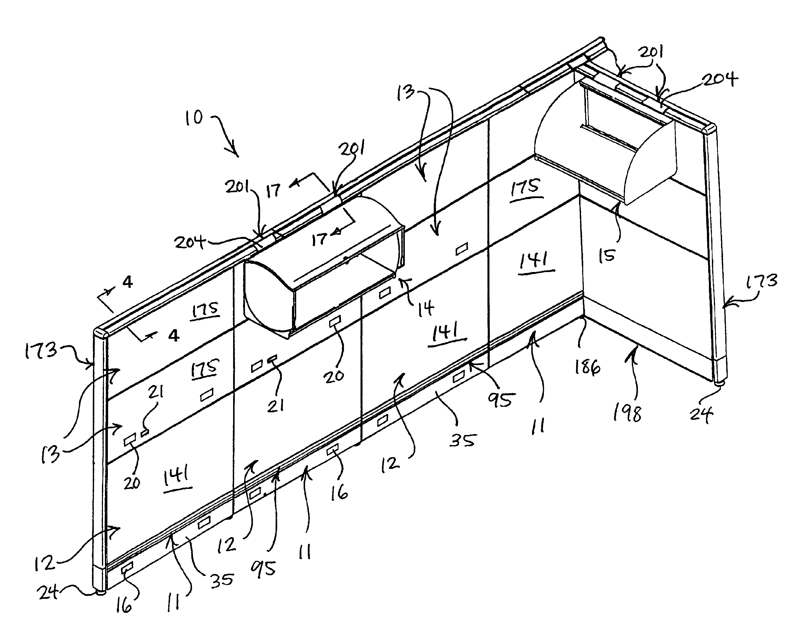
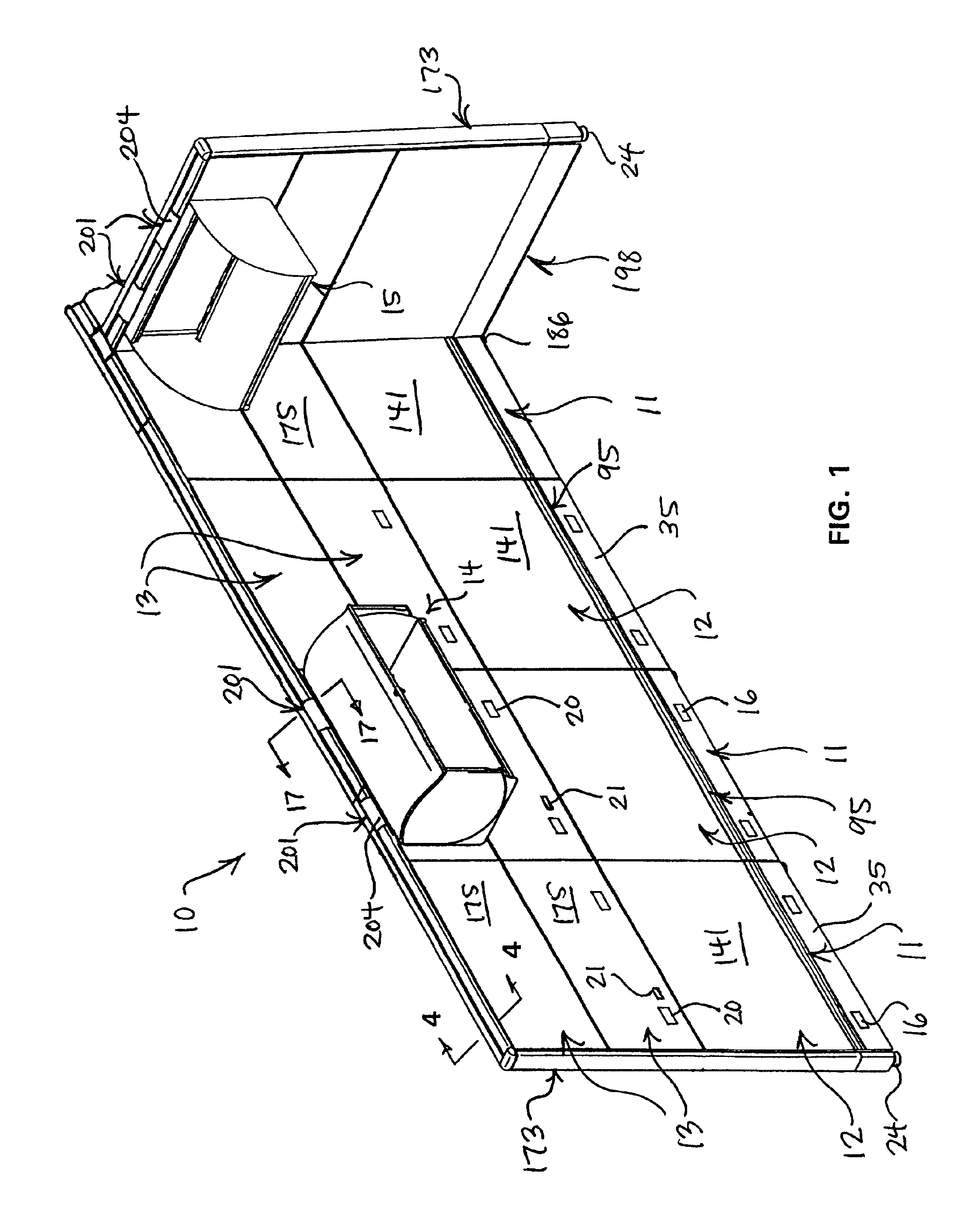
[0030]Referring to FIGS. 1-3, the invention relates to a wall panel arrangement 10 which includes a selected number of upright wall panel assemblies 11 serially connected, for example, in two-panel straight or angled, or three- or four-panel corner configurations so as to subdivide an office area into separate workstations. In the illustrated embodiment, each wall panel assembly 11 includes a base panel assembly 12 supported on a floor and typically includes one or more upper panel assemblies 13 positioned vertically one above the other in a vertical plane.

[0031]Generally, a workstation is defined by a selected arrangement of the base panel assemblies 12 which are serially connected to one another to form at least a lower section of a vertically extending wall. Besides selectively subdividing the office area by the placement of the base panel assemblies 12, the wall panel arrangement 10 permits adjustment of the wall height by selective placement of one or more upper panel assemblie...


PUM


Abstract

A space-dividing wall panel arrangement having a plurality of upright wall panels serially connected one with the other by an upright support post. The wall panel arrangement additionally includes an open-frame structure which allows routing of cabling therethrough to provide power and communication capabilities to a workstation defined by the wall panels, and a removable and rigid top cap which is capable of supporting various furniture-type accessories at selected locations along the longitudinal extent of the panel arrangement, and which also permits mounting of return wall panels to permit greater flexibility in configuring a workstation.

Description

FIELD OF THE INVENTION[0001]This invention relates to a wall panel arrangement formed from upright serially-connected panels joined together by intermediate support posts, and more specifically, to a wall panel arrangement including a top cap which mounts thereon components such as shelves, cabinets and the like.BACKGROUND OF THE INVENTION[0002]Commercial buildings typically include large open office areas which are divided into smaller work spaces or workstations by any of a number of panel systems that have been developed therefor. These panel systems typically employ upright space-dividing wall panels which serially connect together through two panel straight or angled connections, or through suitable three or four panel connections, to subdivide the office area into a plurality of smaller workstations of desired size and configuration. Such panels are typically less than floor-to-ceiling height, and cooperate with other furniture components to define an equipped workstation. The...

Claims


Application Information

Patent Timeline
IPC IPC(8): E04B2/74
CPCE04B2/7433E04B2002/742E04B2002/7461Y10T403/7043E04B2002/7487E04B2002/7488E04B2002/749E04B2002/7483
Inventor YU, X. SHAWNHEYER, STEVEN A.
Owner HAWORTH SPA
Learn More