Tensiometer, drive probe for use with environmental testing equipment, and methods of inserting environmental testing equipment into a sample

a technology of environmental testing equipment and tensiometer, which is applied in the direction of tension measurement, force/torque/work measurement, instruments, etc., can solve the problems of soil gas, drill cuttings being brought to the surface, and the minute amount of water being actually withdrawn

Inactive Publication Date: 2005-07-26
BATTELLE ENERGY ALLIANCE LLC
View PDF9 Cites 11 Cited by
  • Summary
  • Abstract
  • Description
  • Claims
  • Application Information

AI Technical Summary

Problems solved by technology

Prior art uses of cone penetrometer technology for environmental purposes have generally been limited to soil, soil gas, and ground water sampling.
However, because the tube is sealed, only a minute amount of water is actually withdrawn.
Conventional techniques for installing tensiometers require drilling wells with hand augers (if shallow), hollow stem augers, or rotary drill rigs, resulting in drill cuttings being brought to the surface.
In some sites, such as contaminated sites, it is undesirable to have drill cuttings removed to land surface or to have large diameter boreholes drilled.

Method used


Image

  • Tensiometer, drive probe for use with environmental testing equipment, and methods of inserting environmental testing equipment into a sample
  • Tensiometer, drive probe for use with environmental testing equipment, and methods of inserting environmental testing equipment into a sample
  • Tensiometer, drive probe for use with environmental testing equipment, and methods of inserting environmental testing equipment into a sample

Examples


Embodiment Construction

[0017]This disclosure of the invention is submitted in furtherance of the constitutional purposes of the U.S. Patent Laws “to promote the progress of science and useful arts” (Article 1, Section 8).

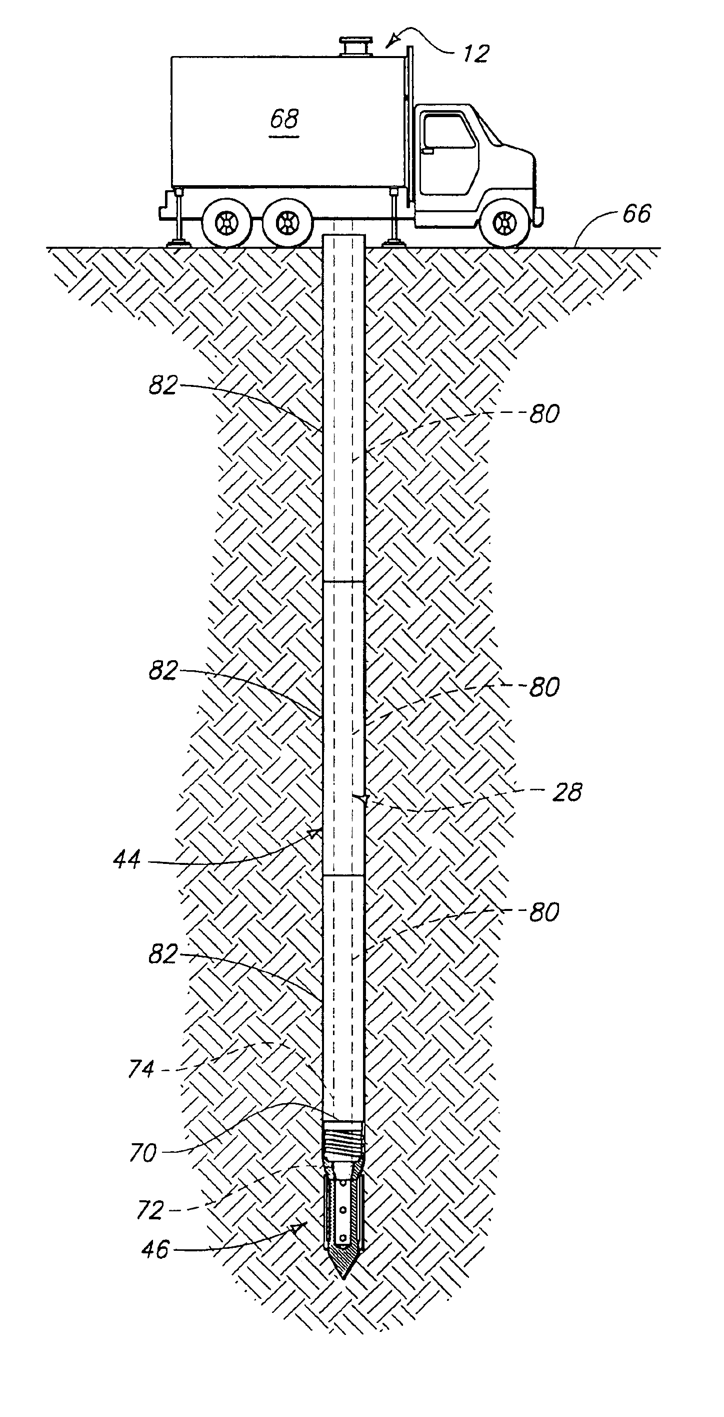
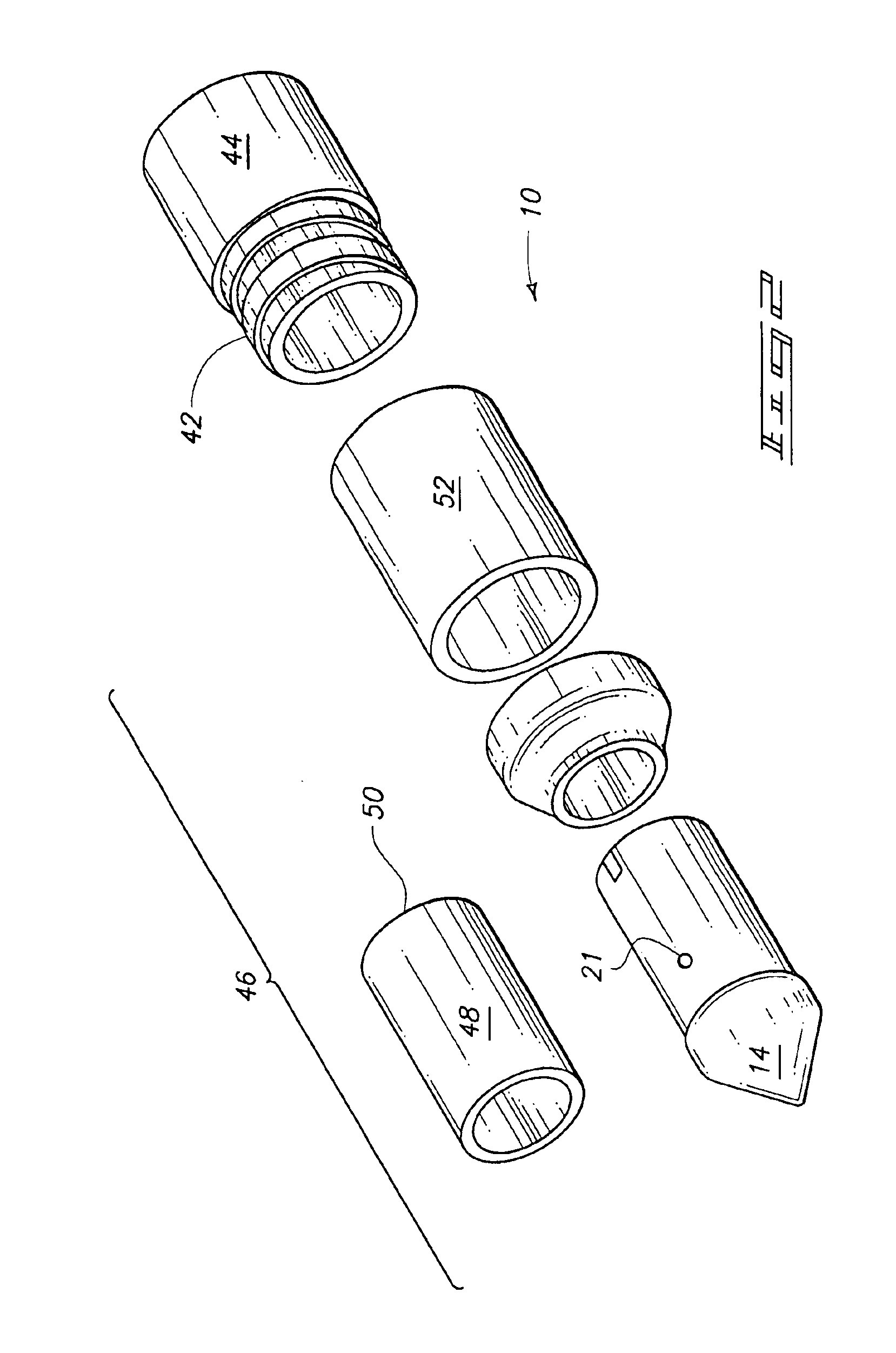
[0018]The invention provides a tensiometer comprising a drive probe configured to be engaged by a drive rod or inner drive tube of direct push equipment; a porous member supported by the drive probe; and a pressure sensor in pressure sensing relation to the porous member.

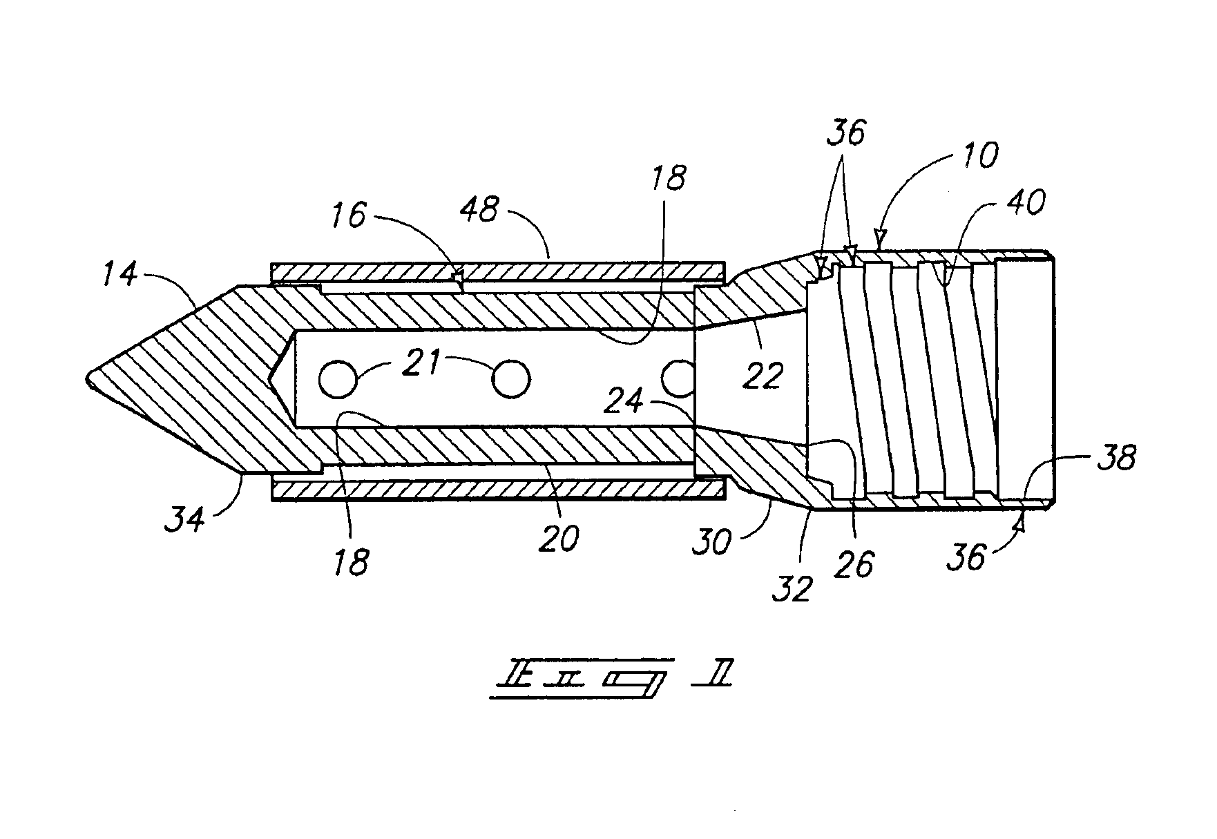
[0019]Another aspect of the invention provides a tensiometer comprising a drive probe including a tip portion, and a hollow elongated portion extending from the tip portion and having an inner surface, an outer surface, and apertures extending between the inner surface and outer surface, the drive probe further including an inner tapered surface in fluid communication with the inner surface of the hollow elongated portion, the tapered surface having a first diameter proximal the tip portion and a second diameter, greater ...


PUM

PropertyMeasurementUnit
diameteraaaaaaaaaa
inner diameteraaaaaaaaaa
strength propertiesaaaaaaaaaa

Abstract

A method of inserting a tensiometer into a sample, comprises providing a drive probe configured to be engaged by direct push equipment; supporting a porous member from the drive probe; and driving the drive probe into the sample using a cone penetrometer. A tensiometer comprises a drive probe configured to be engaged by direct push equipment or a cone penetrometer; a porous member supported by the drive probe; and a pressure sensor in pressure sensing relation to the porous member.

Description

GOVERNMENT RIGHTS[0001]This invention was made with Government support under Contract DE-AC07-99ID13727 awarded by the U.S. Department of Energy. The Government has certain rights in the invention.TECHNICAL FIELD[0002]The invention relates to environmental testing equipment, tensiometers, methods of inserting environmental testing equipment into samples, and methods of manufacturing environmental testing equipment.BACKGROUND OF THE INVENTION[0003]Cone penetrometer technology (CPT) has been used widely for investigating strength properties in foundations and road subgrades for over 40 years, and for environmental purposes for the past five years. Prior art uses of cone penetrometer technology for environmental purposes have generally been limited to soil, soil gas, and ground water sampling.[0004]Tensiometers are known in the art and are described, for example in the following U.S. patents which are incorporated herein by reference: U.S. Pat. No. 5,915,476 to Hubbell et al.; U.S. Pat...

Claims


Application Information

Patent Timeline
Patent Type & Authority Patents(United States)
IPC IPC(8): G01N13/02G01N13/00G01N3/40G01N33/24
CPCG01N3/40G01N13/02G01N33/24
Inventor HUBBELL, JOEL M.SISSON, JAMES B.
Owner BATTELLE ENERGY ALLIANCE LLC
Why Eureka
Try Eureka