Surface light device, image display device and light guide plate

Inactive Publication Date: 2005-07-26
ENPLAS
View PDF13 Cites 38 Cited by
  • Summary
  • Abstract
  • Description
  • Claims
  • Application Information

AI Technical Summary

Benefits of technology

[0008]It is therefore an object of the present invention to suppress abnormal emission in the vicinity of an incidence surface of a light guide plate and surface light source device using LEDs as point light sources or using a fluorescent lamp as a

Problems solved by technology

However, in such a surface light source device 101 using the fluorescent lamp 100A as a linear light source, there is a structural problem in that darker portions (low luminance portions 110 shown by slant lines in FIG. 43) than

Method used


Image

  • Surface light device, image display device and light guide plate
  • Surface light device, image display device and light guide plate
  • Surface light device, image display device and light guide plate

Examples


Example

[0155](Modified Example of Fifth Preferred Embodiment)

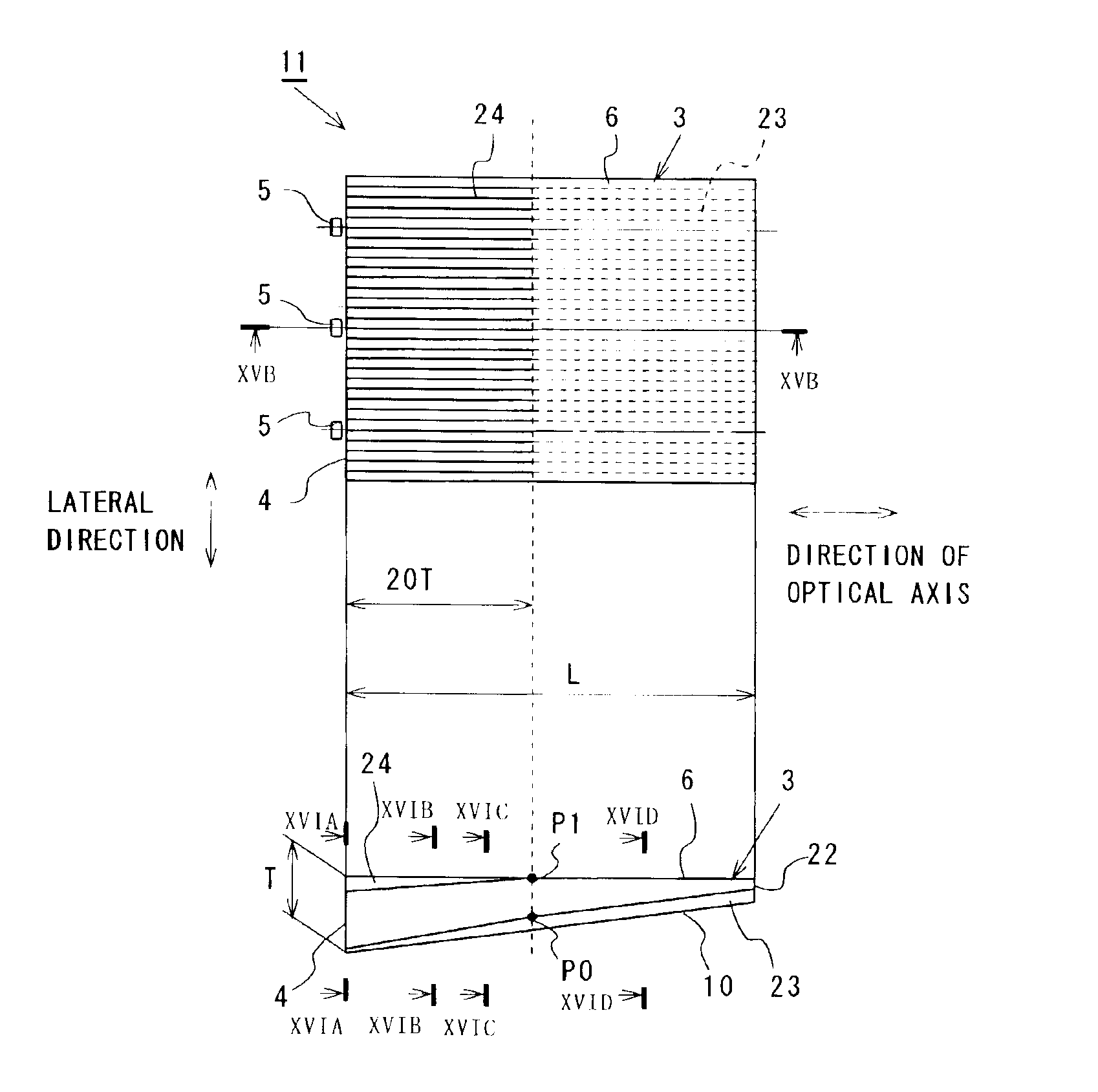
[0156]While the LEDs 5 serving as point light sources have been used in the above described fifth preferred embodiment, a fluorescent lamp 5A serving as a linear light source may be substituted for the LEDs 5 as shown in FIGS. 27A through 27D. In a surface light source device 11 shown in FIGS. 27A through 27D, the same reference numbers are given to the same portions as those in the above described fifth preferred embodiment, and repeated descriptions thereof are omitted. FIG. 27A is a plan view of a light guide plate 3 viewed from the side of an emission surface 6 thereof, FIG. 27B is a sectional view taken along line XXVIIB—XXVIIB of FIG. 27A, FIG. 27C is a sectional view taken along line XXVIIC—XXVIIC of FIG. 27A, and FIG. 27D is a sectional view taken along line XXVIID—XXVIID of FIG. 27A.

[0157]Similar to the light guide plate 3 in the above described fifth preferred embodiment, the light guide plate 3 in this modified example...

Example

[0196](First Example)

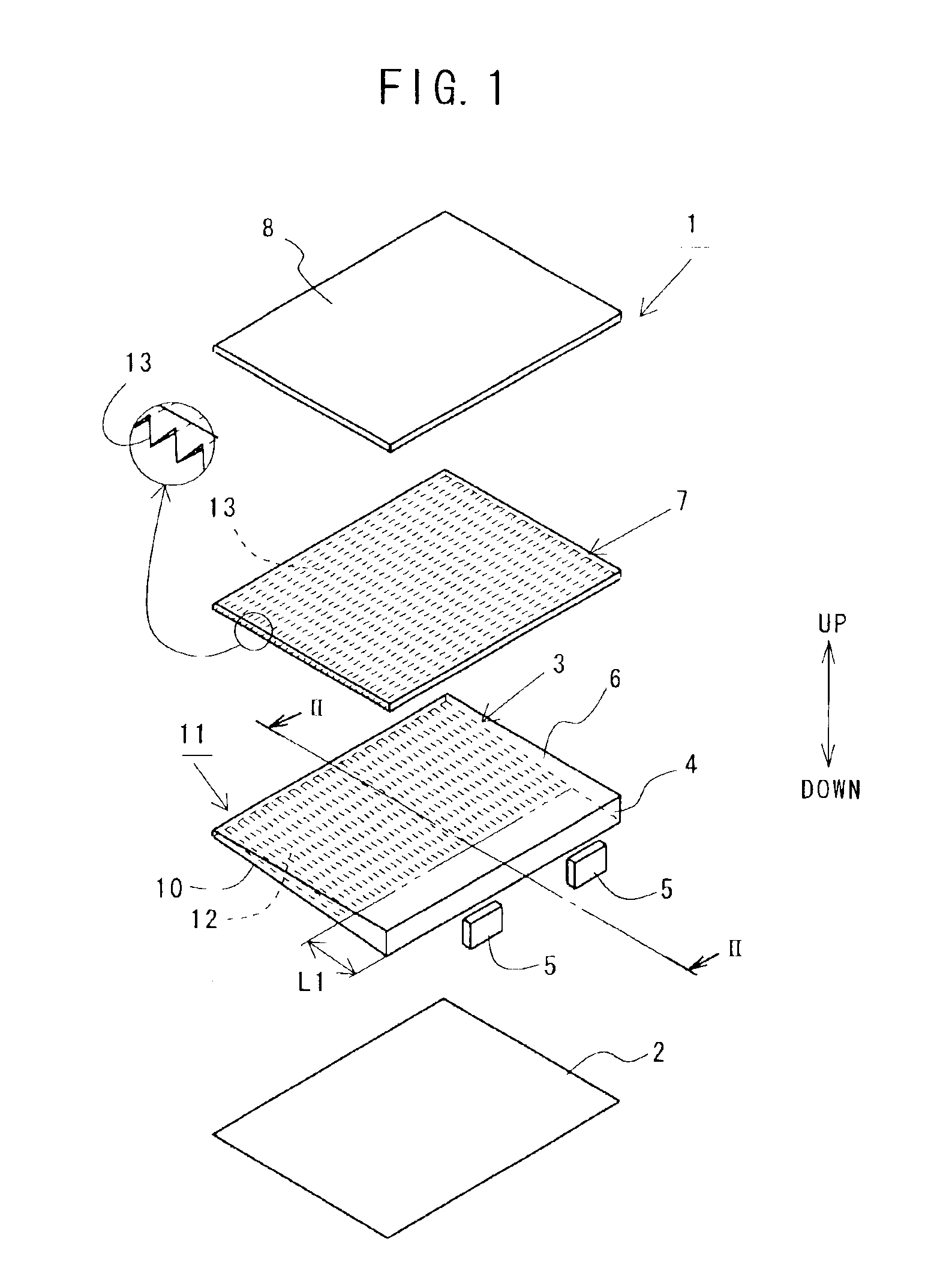
[0197]FIG. 38 shows the twelfth preferred embodiment of the present invention, and is an enlarged view of a part of a sectional shape showing an embodiment of the prism protrusions 13 of the prism sheet 7 arranged on the side of the emission surface 6 of the light guide plate 3 as shown in FIG. 1. The large number of prism protrusions 13 of the prism sheet 7 extend in directions substantially parallel to the incidence surface 4 of the light guide plate 3, and are continuously arranged in directions substantially perpendicular to the incidence surface 4 of the light guide plate 3. FIG. 38 shows a cross section of the prism sheet 7 taken along a line perpendicular to the incidence surface 4 of the light guide plate 3. As an example of the prism sheet 7 in this preferred embodiment, a prism sheet of PMMA will be described below.

[0198]The prism protrusions 13 shown in FIG. 38 are designed to improve the function of reflecting light having directivity, which leaves t...

Example

[0201](Second Example)

[0202]FIG. 39 shows a second example of the prism protrusions 13 of the prism sheet 7. In each of the prism protrusions 13 shown in FIG. 39, one surface 60 comprises two planes of first and second inclined planes 60a and 60b and the other surface 65 comprises two planes of first and second inclined planes 65a and 65b so that the one surface 60 and the other surface 65 are symmetrical with respect to a vertical plane passing through the top of a corresponding one of the prism protrusions 13. The first inclined surfaces 60a and 65a of the one surface 60 and other surface 65 of the prism protrusion 13 are formed at an angle of 34.0 degrees to the normal direction 61, and the second inclined surfaces 60b and 65b thereof are formed at an angle of 30.5 degrees to the normal direction 61. The vertical angle of the prism protrusion 13 is set to be 68 degrees. Both of the one surface 60 and other surface 65 of the prism protrusion 13 serve as the incidence surface and r...


PUM


Abstract

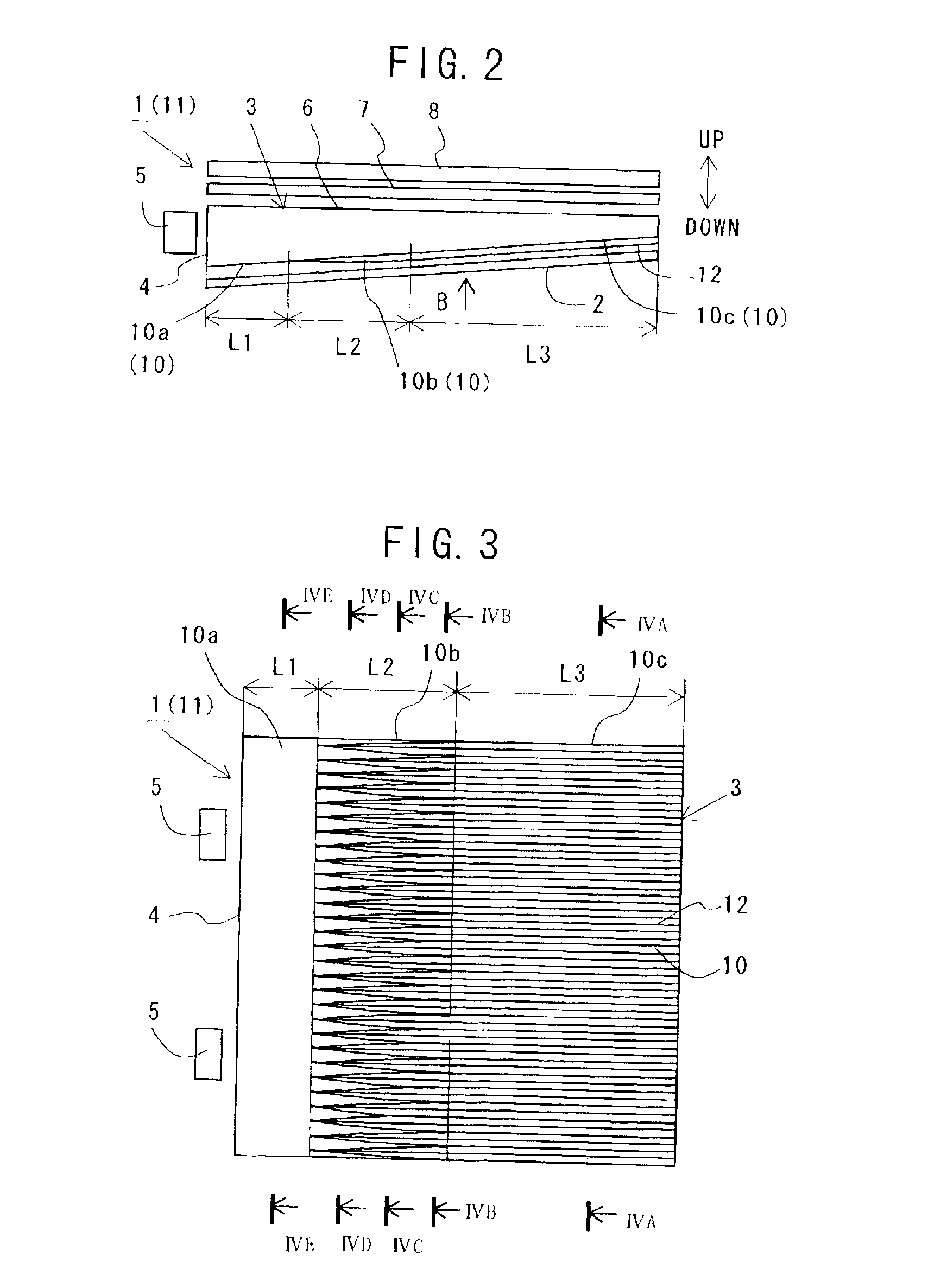
LEDs 5 serving as light sources are arranged so as to face an incidence surface 4 of a light guide plate 3. Light emitted from the LEDs 5 is incident on the incidence surface 4 of the light guide plate 3 to enter the light guide plate 3 to be propagated through the light guide plate 3. When the angle of incidence of the light on an emission surface 6 of the light guide plate 3 is a critical angle or less while the light is propagated, the light leaves the emission surface 6. On at least one of the emission surface 6 of the light guide plate 6 and a surface 10 opposite to the emission surface 6 of the light guide plate 6, a large number of prism protrusions 12 extending in parallel to such a direction that a distance from the incidence surface 4 increases are formed along the incidence surface 4. A side-face side portion 10b of the prism protrusions 12 is formed so as to have a height gradually decreasing as a distance from the incidence surface 4 decreases. With this construction, even if the LEDs are used as light sources, abnormal emission can be suppressed in the vicinity of the incidence surface of the light guide plate, and the luminance of exiting light can be uniform.

Description

TECHNICAL FIELD[0001]The present invention relates to a surface light source device used as a back light or the like for illuminating a plane of a liquid crystal display panel (a member to be illuminated), in portable telephones, portable electronic terminal units, electronic notebooks, car navigation systems, digital cameras, videotape recorders, personal computers, televisions and various office appliances, an image display unit having the surface light source device, and a light guide plate used for the surface light source or image display unit.BACKGROUND ART[0002]A typical one of surface light source devices used for portable telephones, portable electronic terminal units and so forth, has a fluorescent lamp on a side of the side face (on the side of an incidence surface) of a light guide plate as a light source, to emit light to a plane from the fluorescent lamp through the light guide plate to irradiate a liquid crystal display panel with the exiting light. Such a surface lig...

Claims


Application Information

Patent Timeline
IPC IPC(8): F21V8/00G02B6/00F21Y101/02G02F1/1335G02F1/13357
CPCG02B6/0016G02B6/0038G02B6/0068G02B6/004F21Y2101/02G02B6/0036F21V2200/20G02B6/0046G02B6/0053G02B6/0073F21Y2115/10G02F1/1335
Inventor OHKAWA, SHINGO
Owner ENPLAS
Why Eureka
Try Eureka