
Device for mixing a flowable or pourable medium, especially a highly viscous medium

a technology of flowable or pourable medium and high viscosity, which is applied in the direction of mixers, rotary stirring mixers, mechanical instruments, etc., can solve the problems of mass impairing the success of the mixing process, and achieve the effect of high viscosity

Inactive Publication Date: 2005-07-26
VISCO JET RUHRSYST
View PDF13 Cites 12 Cited by
  • Summary
  • Abstract
  • Description
  • Claims
  • Application Information

AI Technical Summary

Benefits of technology

[0006]Based on this, it is an object of the invention to further develop the mixing device of the aforementioned kind such that even media having very high viscosity can be mixed without plugs being formed In the mixing elements.
[0009]A further embodiment, wherein the openings are arranged with rotational symmetry about the entire circumference as well as over the entire length of the peripheral surface area, has the advantage that because of the rotational symmetry of the openings in the mixing elements the radial flow is uniform over all and thus acts across a wide area.
[0011]A preferred configuration of the mixing elements and thus of the openings suggests that the mixing element has the shape of a coil-shaped spiral. The basic idea resides in that the peripheral surface area is defined by a spiral coil (or coil-shaped spiral). This provides a very open structure, i.e., a spiral structure through which the plug formations can escape substantially radially through the intermediate spaces between the windings of the spiral. In addition to these method-based advantages, this mixing element of a spiral shape can also be produced technically in a very simple way.
[0012]The advantage of the further embodiment according to which the thickness of the wire of the spiral matches approximately the spacing between two windings of the spiral resides in that an optimal ratio between the axially passing medium and the radially flowing medium is provided.
[0013]The further embodiment according to which the support arm and the spiral form a monolithic part has the advantage that the unit comprised of support arm and mixing element can be produced technically in a very simple way from a single piece, i.e., form a single wire, wherein the thickness of the support arm is identical to the thickness of the windings of the spiral.

Problems solved by technology

In particular in the case of media having a very high viscosity, there is the risk in the case of the known mixing devices that a plug will form within the conically shaped mixing elements so that medium can no longer flow through the mixing element.
This massively impairs the success of the mixing process.

Method used


Image

  • Device for mixing a flowable or pourable medium, especially a highly viscous medium
  • Device for mixing a flowable or pourable medium, especially a highly viscous medium
  • Device for mixing a flowable or pourable medium, especially a highly viscous medium

Examples


Embodiment Construction

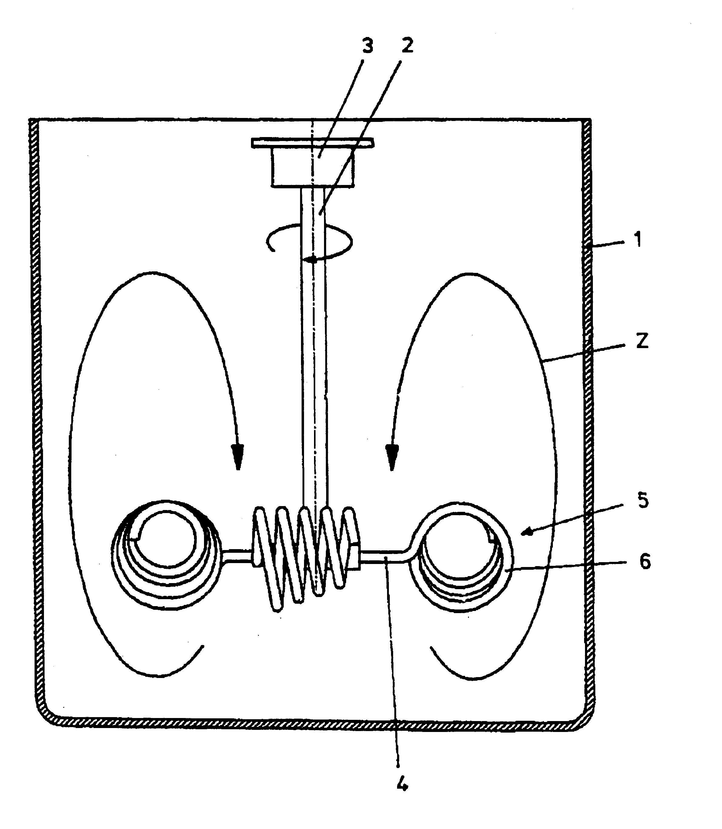
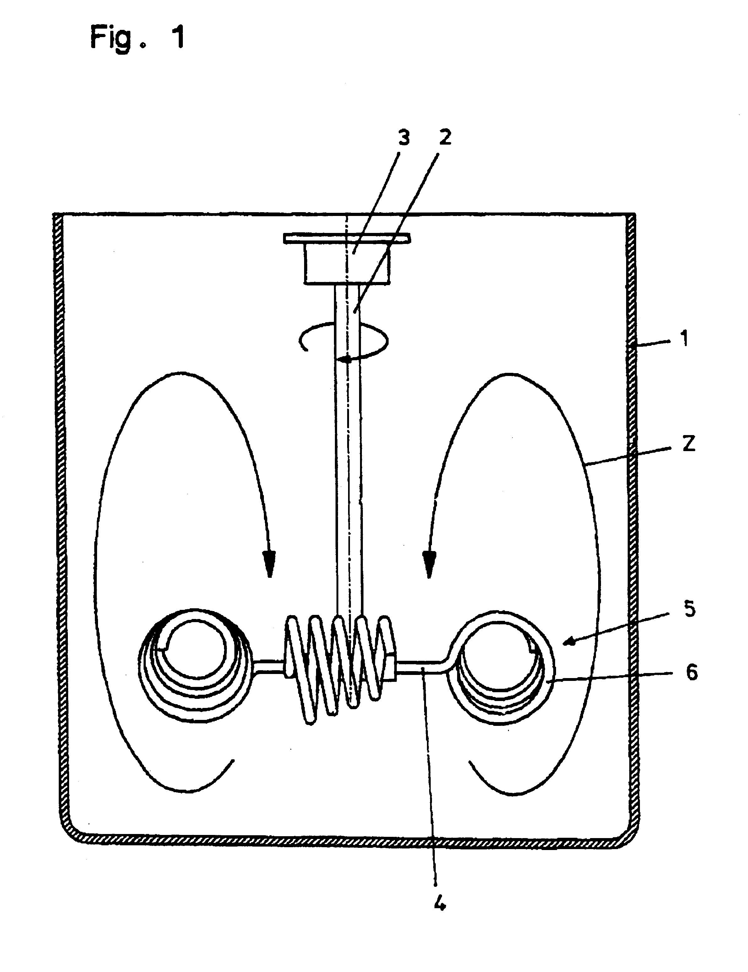
[0023]The mixing device has a cylindrical container 1. From above, a shaft 2 is immersed into the container 1. It has at its upper end a coupling 3 which allows connection of the shaft 2 to a drive motor, not illustrated. In the illustrated embodiment, the shaft 2 is vertically arranged. However, it is also conceivable to position the shaft 2 at a slant.

[0024]At the lower end of the shaft 2, four wire-shaped support arms 4 project radially. A mixing element 5 is arranged at the forward end of each one of the support arms 4, respectively. The mixing elements 5 are formed by a coil-shaped spiral 6. This coil-shaped spiral 6 forms the peripheral surface area of a truncated cone. The windings of the spiral 6 define openings 7 therebetween. The two end faces of the cone are open, respectively. As illustrated in FIG. 3, the central axis M of the spiral 6 is positioned at a slant angle α relative to the rotational plane of the mixing elements 5. The support arm 4 and the spiral 6 of the mi...


PUM


Abstract

A device for mixing a flowable or pourable medium has a container for receiving the medium and a rotatable shaft having radially projecting support arms and rotatable in a direction of rotation. Mixing elements are connected to the radially projecting support arms. The mixing elements are tubular and formed as coil-shaped spirals conically shaped at least across a partial length of the coil-shaped spirals. The coil-shaped spirals have a first end face and a second end face. The first end face points in the direction of rotation and has a cross-section greater than the cross-section of the second end face. The coil-shaped spirals have a central axis having a slant angle relative to a plane of rotation of the two mixing elements. The support arms and the coil-shaped spirals connected to the support arms, respectively, are formed of a single wire as a monolithic part, respectively.

Description

BACKGROUND OF THE INVENTION[0001]The invention relates to a device for mixing a flowable or pourable medium, in particular, a viscous medium. The device comprises a container receiving the medium as well as at least two mixing elements arranged on a rotatable shaft on substantially radially projecting support arms, wherein the mixing elements are tubular with open end faces and are conically shaped at least across an area of partial length, wherein the end face pointing in the direction of rotation has the greater cross-section and wherein the central axis has a slant angle relative to the plane of rotation.[0002]The mixing device according to the invention is suitable for low viscosity to high viscosity fluids. The special field of application are fluids of very high viscosity. Moreover, the mixing device according to the invention is suitable for pourable solids.[0003]The mixing device of the aforementioned kind is known from DE 39 01 894 C2. This mixing device particularly for hi...

Claims


Application Information

Patent Timeline
IPC IPC(8): B01F15/00B01F7/00B01F7/16
CPCB01F7/00558B01F7/00591B01F27/118B01F27/15B01F27/80
Inventor WEBER, HANS
Owner VISCO JET RUHRSYST
Learn More