Centrifugal slurry pump

a centrifugal slurry pump and centrifugal technology, applied in the field of centrifugal slurry pumps, can solve the problems of recirculating eddy current impingement wear, potentially very abrasive environment of slurry pumps, etc., to improve erosion characteristics, improve wear characteristics, and minimize pump wear.

Inactive Publication Date: 2005-07-26
BLATTMANN URS
View PDF12 Cites 7 Cited by
  • Summary
  • Abstract
  • Description
  • Claims
  • Application Information

AI Technical Summary

Benefits of technology

[0005]With the foregoing in mind, the present invention advantageously provides a centrifugal slurry pump which minimizes the pump wear which occurs as a result of impingement erosion of pump components by the slurry. The present invention, therefore, provides a slurry pump with improved wear characteristics.
[0006]The present slurry pump has improved erosion characteristics and comprises a rotatable impeller, an impeller shroud, and a pump housing. The rotatable impeller having at least one impeller vane and impeller shroud, and which has an inlet for conveying slurry to the impeller and an outlet for discharging slurry accelerated by the impeller. A pump housing has a side wall with a recess therein, the recess being deep enough to therein engage the shroud outlet so as to form a joint surface producing an impingement angle sufficient to substantially reduce impingement erosion thereon by the accelerated slurry discharged by the impeller through the outlet.

Problems solved by technology

Slurry pumps are used in the hydraulic transport of these slurries and, depending on the physical hardness of the suspended solids, slurry pumps must operate in potentially very abrasive environments.
The root cause of this problem is the recirculating eddy current impingement wear that occurs as the solids-laden slurry exits the impeller outlet and enters the pump housing.

Method used


Image

  • Centrifugal slurry pump
  • Centrifugal slurry pump
  • Centrifugal slurry pump

Examples


Embodiment Construction

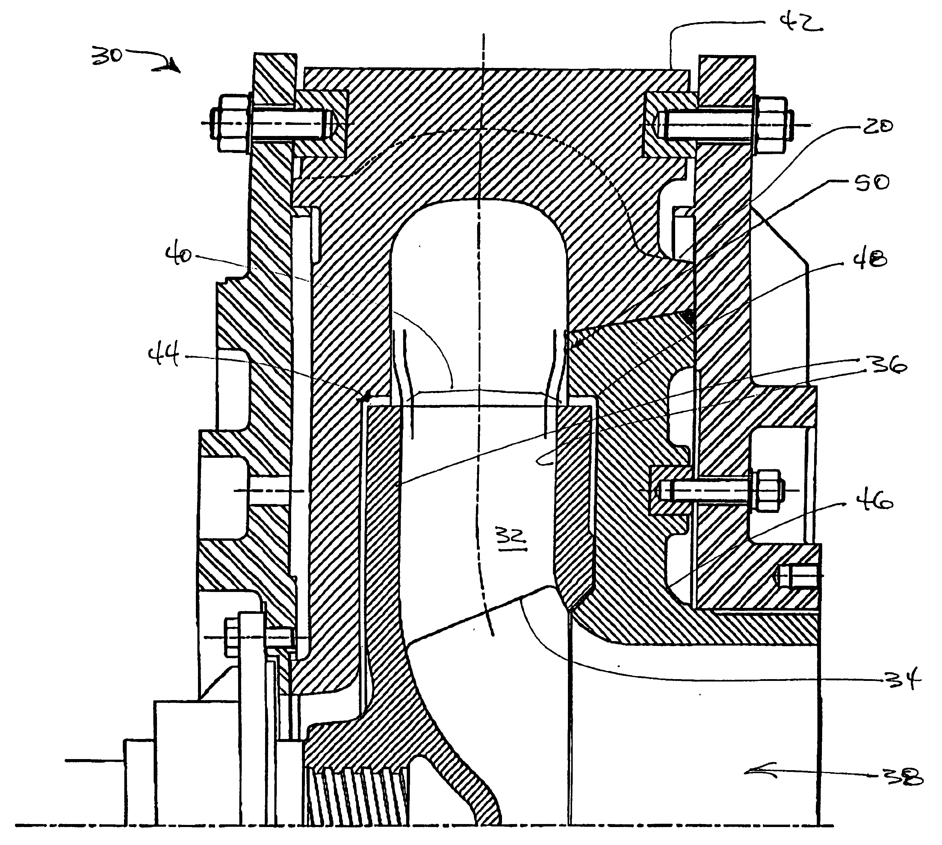
[0013]The present invention will now be described more fully hereinafter with reference to the accompanying drawings, in which preferred embodiments of the invention are shown. This invention may, however, be embodied in many different forms and should not be construed as limited to the illustrated embodiments set forth herein. Rather, these illustrated embodiments are provided so that this disclosure will be thorough and complete, and will fully convey the scope of the invention to those skilled in the art.

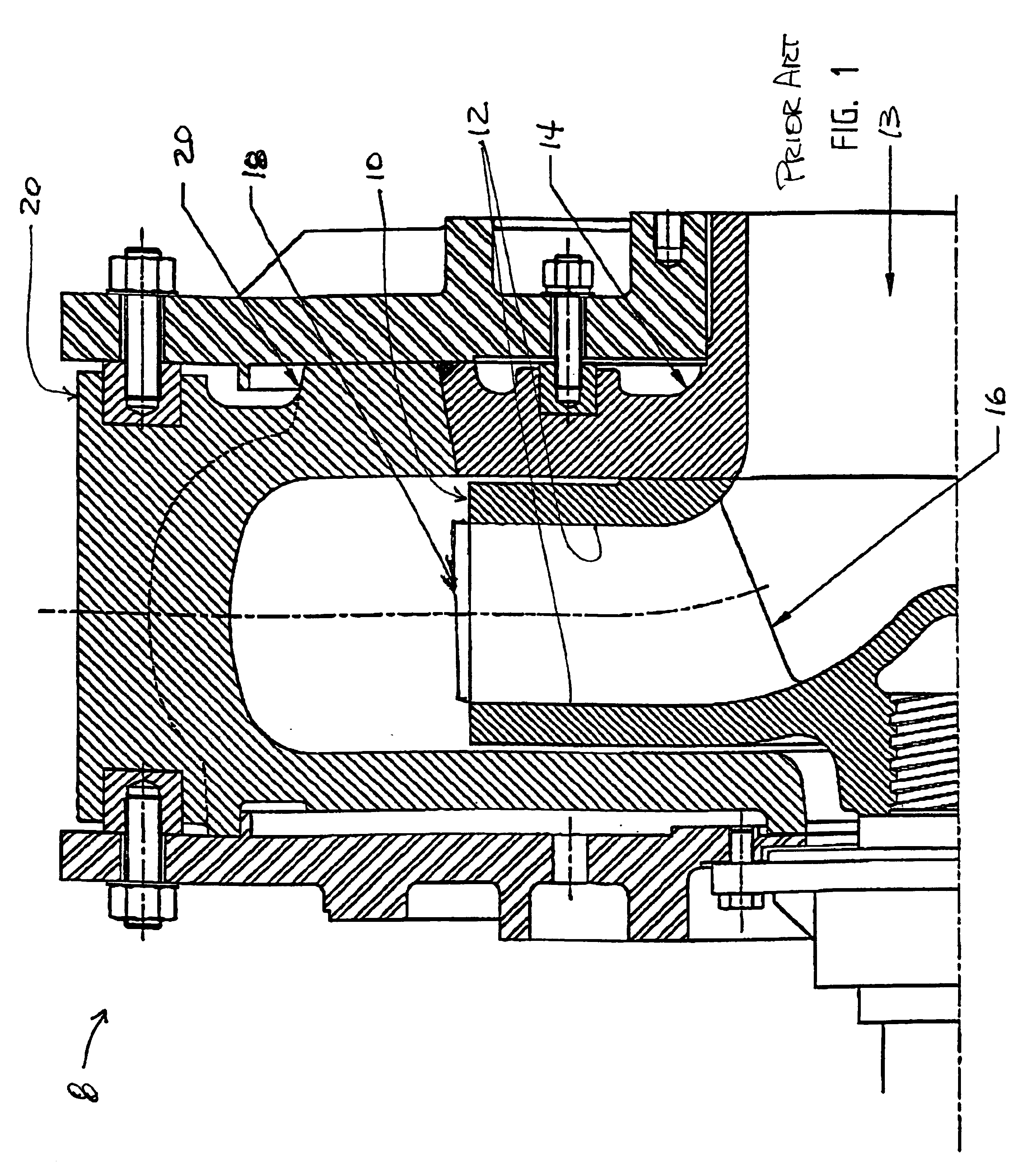
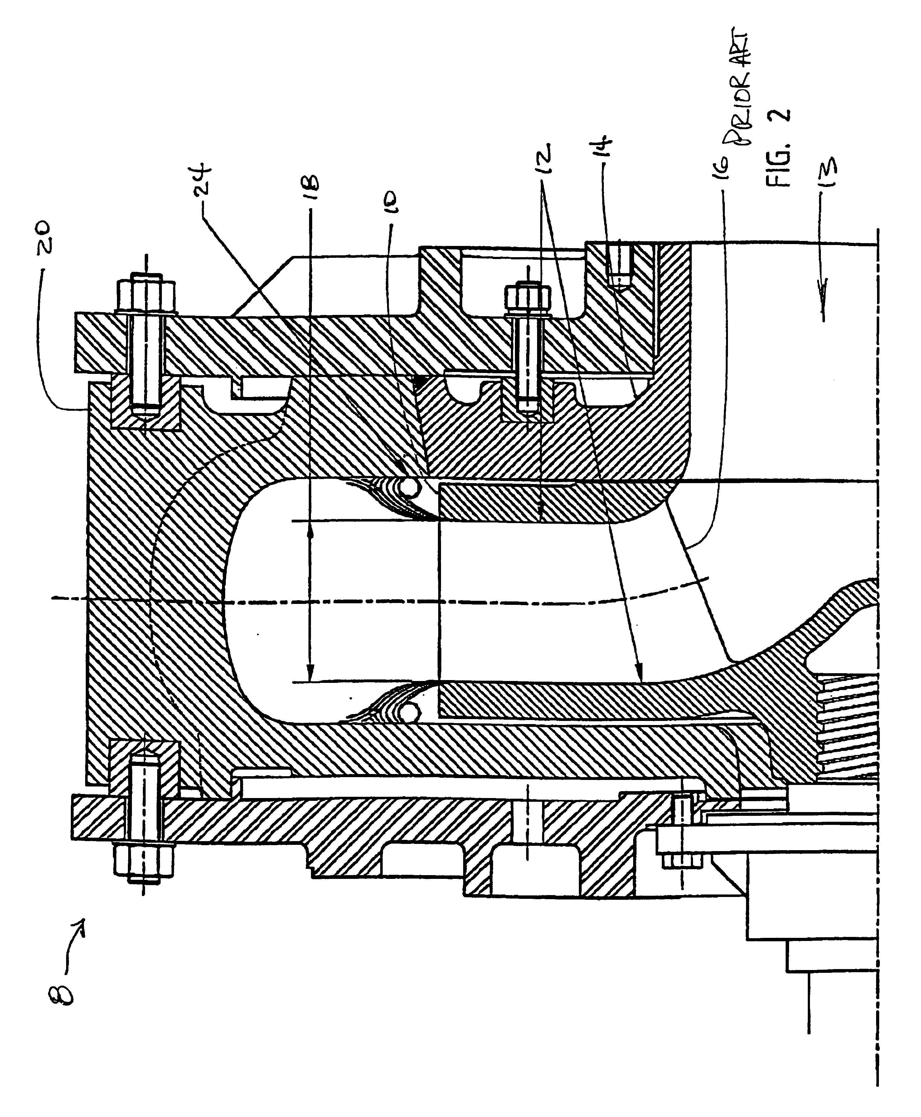
[0014]Depicted in FIG. 1 is a common configuration for a typical prior art slurry pump 8, which comprises a rotating impeller 10 having an impeller shroud 12. Located adjacent the impeller is a stationary suction liner 14 which is intended to protect the susceptible portions of the impeller shroud 12 from wear due to erosion by the slurry entering the impeller by an inlet 13. As the impeller 10 rotates, it creates a low pressure zone in the inlet and slurry is forced into the imp...


PUM


Abstract

An apparatus and method for a slurry pump having improved erosion characteristics. The pump comprises a rotatable impeller having at least one impeller vane, an impeller shroud having an inlet for conveying slurry to the impeller and an outlet for discharging slurry accelerated by the impeller, and a pump housing having a side wall with a recess therein, said recess being deep enough to therein matingly receive said impeller shroud outlet so as to form a joint surface producing a sufficient impingement angle between the impeller shroud outlet and the pump housing side wall to substantially reduce erosion thereon by the accelerated slurry.

Description

RELATED APPLICATION[0001]This application claims priority from co-pending provisional application Ser. No. 60 / 304,295, which was filed on Jul. 10, 2001, and which is incorporated herein by reference in its entirety.FIELD OF THE INVENTION[0002]The present invention relates to the field of pumps and, more particularly, to a centrifugal slurry pump having improved wear characteristics.BACKGROUND OF THE INVENTION[0003]A slurry is formed by suspending a ground solid in a liquid. Slurries are employed for transporting ground solids in operations such as mining, marine dredging, and others. Slurry pumps are used in the hydraulic transport of these slurries and, depending on the physical hardness of the suspended solids, slurry pumps must operate in potentially very abrasive environments.[0004]The mechanics of “wear” in a centrifugal slurry pump are multifaceted and vary depending on the overall hydraulic design of the system and of the pump itself, as well as the operating conditions in te...

Claims


Application Information

Patent Timeline
Patent Type & Authority Patents(United States)
IPC IPC(8): F04D29/44
CPCF04D29/445F04D7/04Y10S415/914
Inventor BLATTMANN, URS
Owner BLATTMANN URS
Why Eureka
Try Eureka