Traction stirrup insert

a technology of inserts and stirrups, which is applied in the direction of fastening devices, domestic applications, animal husbandry, etc., can solve the problems of inserts being easily dislodged, frequent and substantial variations in the dynamic force between the rider's foot, and compounding problems, so as to improve the wear characteristics, prevent sliding, and enhance the effect of force transfer

Inactive Publication Date: 2005-02-24
ZUCCHINI MICHAEL R
View PDF18 Cites 8 Cited by
  • Summary
  • Abstract
  • Description
  • Claims
  • Application Information

AI Technical Summary

Benefits of technology

[0009] In this regard, the present invention provides for a traction enhancing insert assembly that is installed into the foot plate of stirrups. The insert assembly of the present invention is formed from milled aluminum. The milled aluminum plate provides a durable surface that has greatly improved wear characteristics as compared to the prior art. The assembly includes a top traction surface that is placed onto the foot plate of the stirrup. A mounting plate is placed beneath the stirrup and connected to the underside of the traction surface using fasteners. Since the insert is rigidly fixed to the stirrup using fasteners, the insert is prevented sliding in the stirrup like the inserts of the prior art. In this manner, the rigid relation ship between the insert and the foot plate of the stirrup allows for enhanced force transfer from the rider's foot into the stirrup with a greatly reduced potential for the insert to slip relative to the stirrup.
[0010] To further enhance the rigid relationship between the insert and the foot plate of the stirrup, a resilient gasket material may be provided between the bottom of the traction surface and the foot plate of the stirrup before the mounting plate and fasteners are installed. Once the fasteners are tightened the gasket is compressed to retain the insert in the installed position.
[0011] An additional feature that enhances the functionality pf the device is the provision of raised structures, such as pyramidal shaped lugs, on the top of the traction surface to provide an enhanced grip between the stirrup and the rider's shoes. Further, since the material from which the insert is fabricated is durable, wear of the insert is greatly reduced.
[0012] Accordingly, one of the objects of the present invention is the provision of a durable and rigidly attached traction insert for a stirrup. Another object of the present invention is the provision of a removable stirrup insert that is rigidly mounted to the foot plate of the stirrup that eliminates the possibility of the insert becoming dislodged during demanding equestrian maneuvers. A further object of the present invention is the provision of a durable, rigid traction insert for a stirrup that is rigidly attached to the foot plate of a stirrup in a manner that prevents both the insert and the rider's foot from shifting when placed under a high degree of lateral loading.

Problems solved by technology

In jumping, the problem is compounded by increased dynamic forces generated directly and the point where the rider's foot is in contact with the stirrups.
Should contact be lost, the riser cannot maintain the proper balance and suspension required to remain on the horse, as a result the rider's foot may slip out of the stirrup in the middle of a jumping maneuver with disastrous consequences.
Therefore, in this environment a rider would encounter both normal riding conditions and jumping conditions in rapid and alternating succession resulting in frequent and substantial variations in the dynamic forces between the rider's foot and the stirrup.
While this configuration is well suited to the forces exerted during casual riding, these inserts are easily dislodged during more strenuous riding maneuvers, particularly jumping.
These pads however are easily torn from the metal arms under the dynamic stresses encountered in jumping.
Further, because the fastening means provides a small degree of latitude in lateral motion, the arms are subjected to a high degree of dynamic stress causing them to bend or break.

Method used


Image

  • Traction stirrup insert
  • Traction stirrup insert
  • Traction stirrup insert

Examples


Embodiment Construction

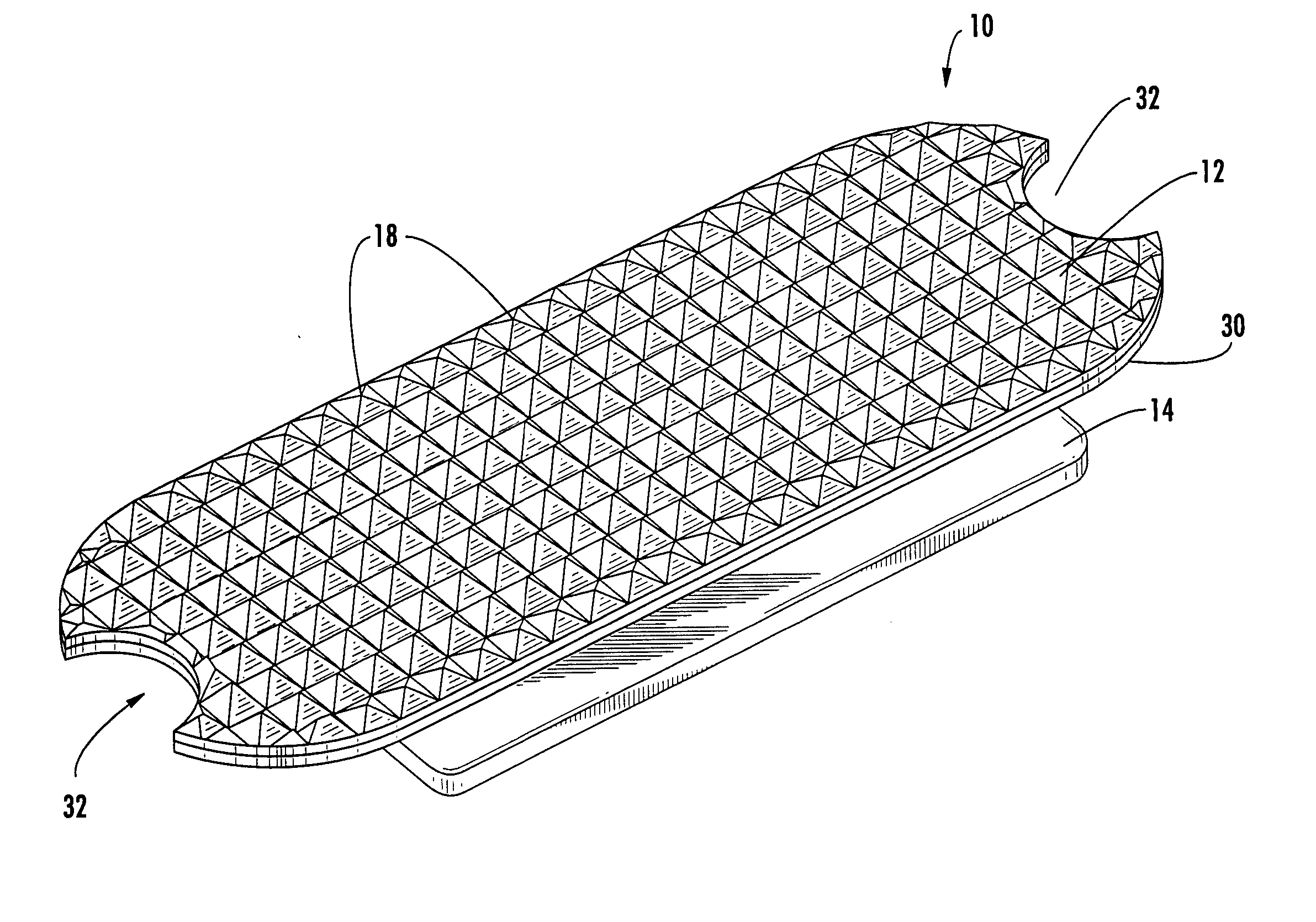
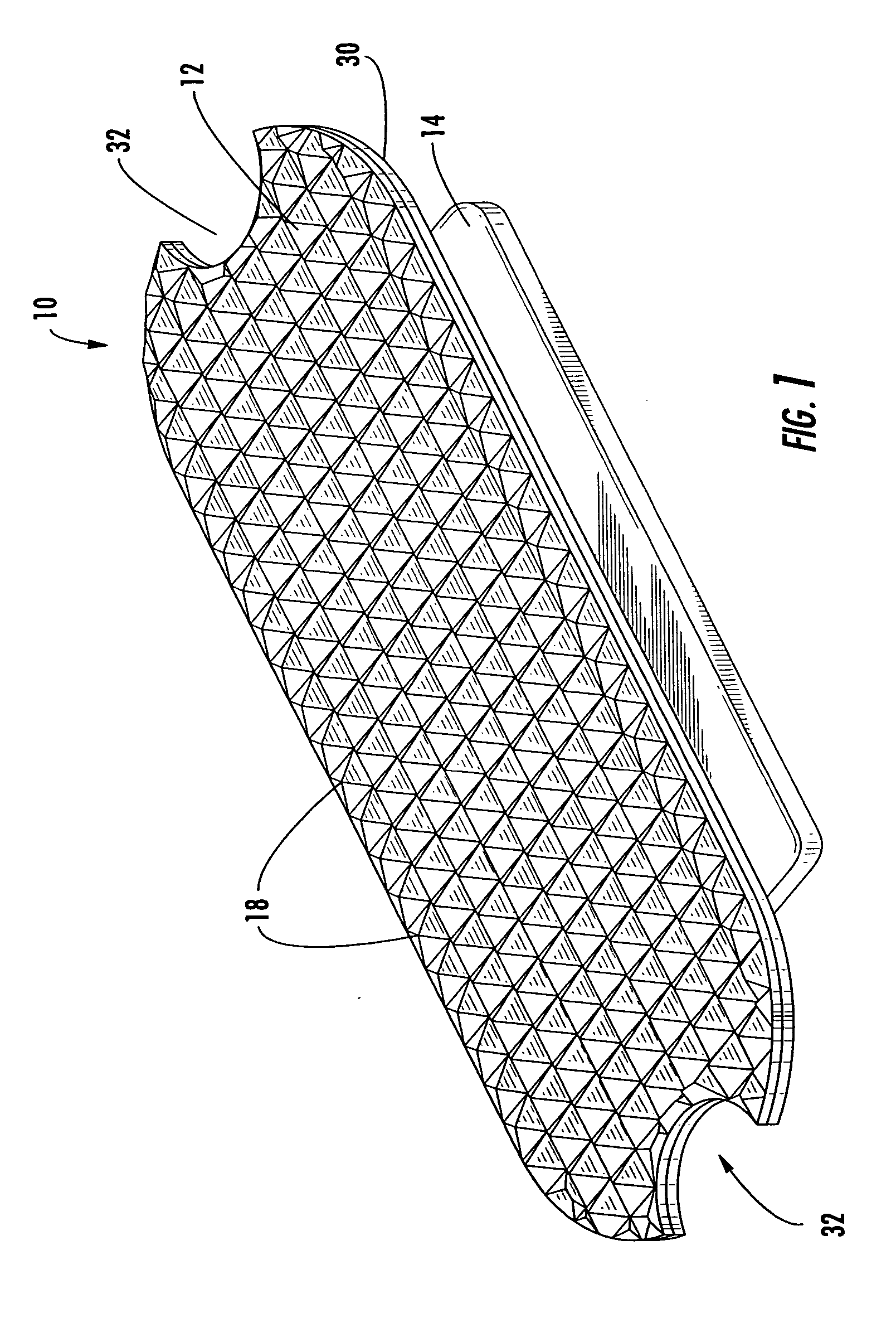
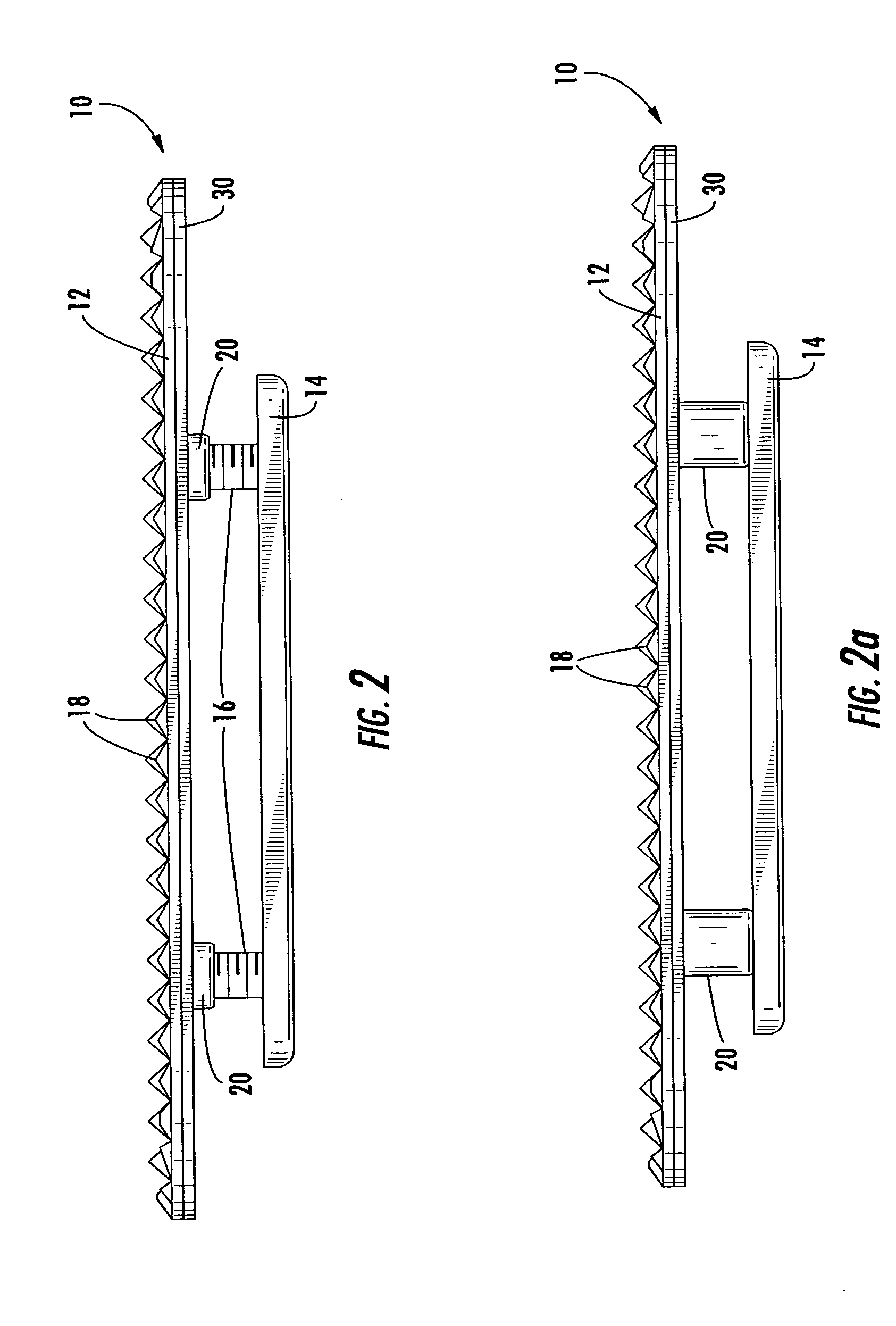
[0020] Referring now to the drawings, the traction insert assembly of the present invention is illustrated and generally indicated at 10 in FIGS. 1-4. As will hereinafter be more fully described, the traction insert 10 generally includes a top traction plate 12, a bottom mounting plate 14 and fasteners 16 to connect the top traction plate 12 and bottom mounting plate 14 to one another. In general terms, the traction plate 12 is placed above the foot plate of an equestrian stirrup, the mounting plate 14 is placed below the foot plate and the two pieces are fastened in a fixed position around the foot plate. The present invention therefore provides a convenient and durable traction insert 10 for a stirrup that has not been previously available in the prior art.

[0021] Turning to FIGS. 1 and 2, it can be seen that the traction insert 10 includes a top traction plate 12. The top traction plate 12 can be formed from any suitable material. In the preferred embodiment the traction plate 12...


PUM


Abstract

An equestrian stirrup insert for enhancing the stability and traction of the stirrup foot plate. In this regard, the present invention provides for a traction enhancing insert assembly that is installed into the foot plate of stirrups. The insert is formed from milled aluminum. The milled aluminum plate provides a durable surface that has greatly improved wear characteristics. The assembly includes a top traction surface that is placed onto the foot plate of the stirrup. A mounting plate is placed beneath the stirrup and connected to the underside of the traction surface using fasteners. Since the insert is rigidly fixed to the stirrup using fasteners, the insert is prevented sliding in the stirrup. In this manner, the rigid relation ship between the insert and the foot plate of the stirrup allows for enhanced force transfer from the rider's foot into the stirrup with a greatly reduced potential for the insert to slip relative to the stirrup.

Description

CROSS-REFERENCE TO RELATED APPLICATIONS [0001] This application is related to and claims priority from earlier filed design patent application Ser. No. 29 / 183,316, filed Jun. 10, 2003.BACKGROUND OF THE INVENTION [0002] The present invention relates generally to a stirrup insert for use in equestrian riding. More particularly, the present invention relates to a stirrup insert that is rigidly attached to an equestrian riding stirrup to improve the traction of the stirrup and better retain the rider's foot under demanding riding conditions. [0003] Typical equestrian riding gear includes a saddle with stirrups attached to straps extending from the saddle for receiving the feet of a rider. Clearly, the stirrups are an integral part of the riding equipment used by most equestrian riders. In general, riders use stirrups to retain or secure their feet thereby allowing them to maintain their balance while riding and while performing various riding maneuvers. Moreover, riders use stirrups to ...

Claims


Application Information

Patent Timeline
Patent Type & Authority Applications(United States)
IPC IPC(8): B68C3/00
CPCB68C2003/0091B68C3/00
Inventor ZUCCHINI, MICHAEL R.
Owner ZUCCHINI MICHAEL R
Why Eureka
Try Eureka