
Fine grained sintered cemented carbide, process for manufacturing and use thereof

Inactive Publication Date: 2007-02-20
KENNAMETAL INC
View PDF10 Cites 9 Cited by
  • Summary
  • Abstract
  • Description
  • Claims
  • Application Information

AI Technical Summary

Benefits of technology

[0012]The object of the invention is therefore to provide novel, fine grained and at the same time corrosion-resistant sintered cemented carbide grades having improved high temperature properties, in particular having improved wear characteristics in the metal cutting test, which may be employed for all kinds of metal cutting purposes and used in particular for the manufacture of cutting inserts and other cutting tools, but also for the manufacture of heavily stressed parts subject to wear, such as, e.g., rollers.
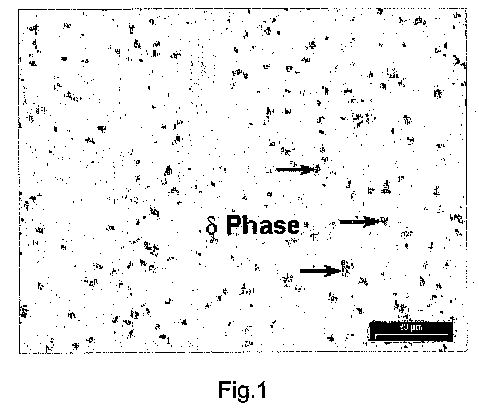
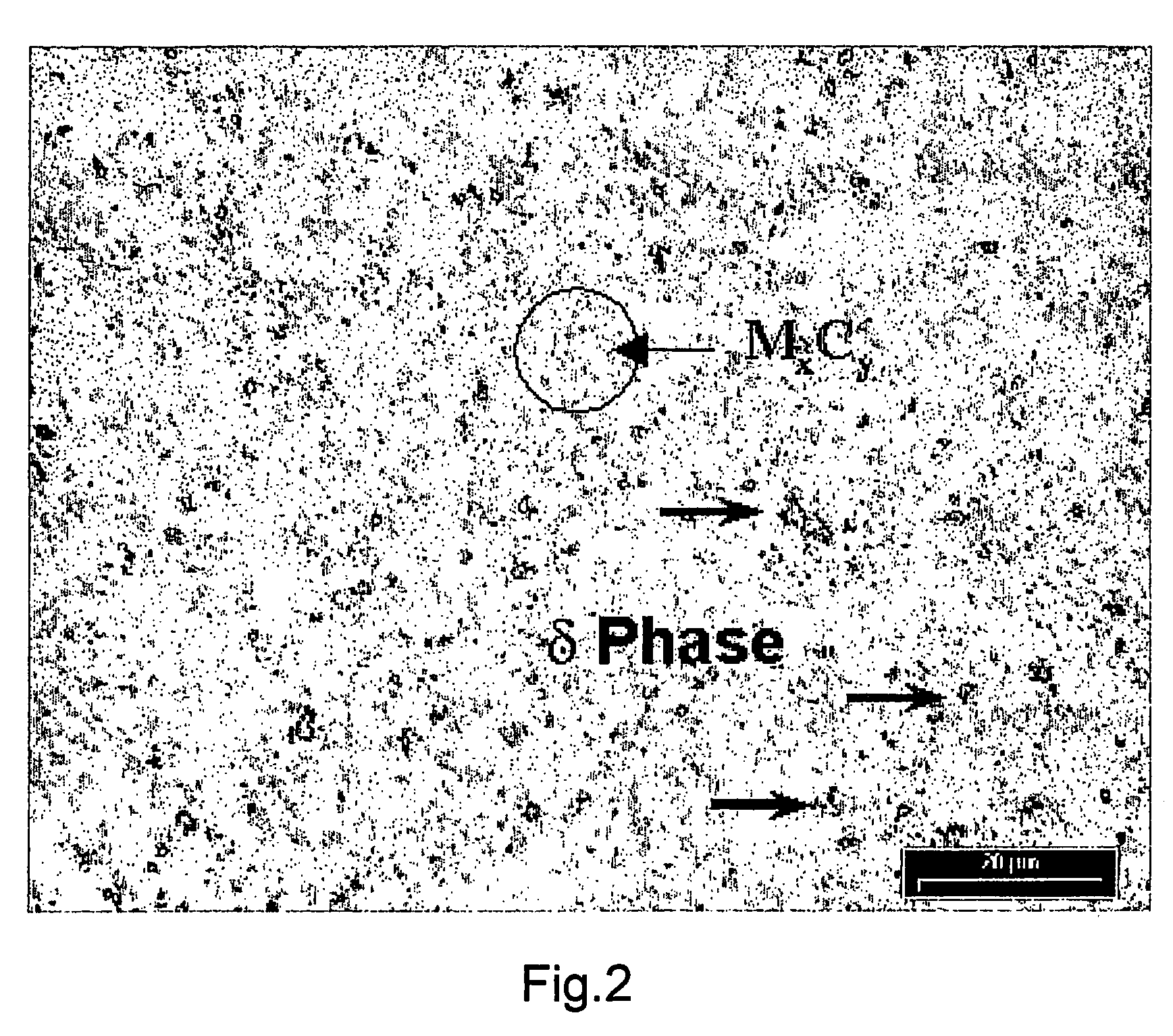
[0014]The applicants have surprisingly succeeded in providing, for the first time, a fine grained sintered cemented carbide containing chromium, in which a good trade-off between hardness and bending strength is attained by an effective suppression or restriction of grain growth, on the one hand by the addition of a grain growth inhibitor known per se, namely TaC or (Ta,Nb)C, and on the other hand by the use of a fine, submicron and / or ultrafine tungsten carbide powder, and in which furthermore the solubility of the tantalum in the binder phase at room temperature is exceeded by the addition of tantalum in relatively large amounts of up to approximately 4 mass-% in the presence of chromium at the same time, so that an additional phase precipitates which comprises a TaC phase visible in the sintered cemented carbide by optical microscopy. The saturation of the binder phase with Ta and the simultaneous presence of chromium in the solid solution of the binder phase, and the precipitation of the additional TaC phase in the form of a discrete phase visible by optical microscopy, improve the deformation behavior, the resistance to scaling and diffusion and, above all, the high temperature properties of the cemented carbide in accordance with the invention and the shaped bodies produced therefrom to such an extent that, unlike the grades disclosed in German Patent 40 00 223 and U.S. Pat. No. 5,918,102, the cemented carbide grades in accordance with the invention may even and in particular be utilized for metal cutting purposes where extremely high temperatures and heavy thermal shock stresses can occur. This considerably broadens the previously known ranges of application of submicron and ultrafine sintered cemented carbides in the field of metal cutting, something which is totally surprising among expert circles in view of the prior art.

Problems solved by technology

The harder a cemented carbide grade, the better its wear resistance, but the worse its bending strength.
Grain growth is almost impossible to avoid during sintering and hot isostatic pressing (HIPping) of the corresponding green compacts and has a negative effect on the bending strength of the sintered cemented carbide.
The complexity of the process sequences in cemented carbide manufacturing is still further increased in that both tungsten from the tungsten carbide and the metals of the grain growth inhibitors diffuse into the binder phase and dissolve therein to form a solid solution.
Such deposition, however, impairs the wetting of the grains with the binder metal, which in turn results in a deterioration in the bending strength.
It turned out, however, that the cemented carbide grades mentioned in the two patents are not so suitable for metal cutting purposes, in particular for the cutting of steel, because they do not have the necessary high temperature properties (high temperature hardness, resistance to scaling and diffusion, wear characteristics in the cutting test).

Method used


Image

  • Fine grained sintered cemented carbide, process for manufacturing and use thereof
  • Fine grained sintered cemented carbide, process for manufacturing and use thereof
  • Fine grained sintered cemented carbide, process for manufacturing and use thereof

Examples


example 1

[0065]Cutting inserts of the SPGN 120308F geometry were made from the X and Y powder blends and were subjected to a metal cutting test under the following conditions:[0066]Material of the workpiece to be cut: C45 steel[0067]Cutting speed: 100 m / min.[0068]Feed rate: 0.15 mm / revolution[0069]Depth of cut: 1.0 mm[0070]Coolant: none[0071]Result: The tool life of the cutting insert made from the X powder blend (prior art) amounted to 6.4 min. until a maximum possible wear of the flank face of 0.25 mm was reached, whereas the tool life of the cutting insert according to the invention made from the Y powder blend amounted to 9.6 min., which corresponds to a 50% increase.

[0072]Further cutting inserts of the SPGN120308F geometry, made from the X and Y powder blends, were subjected to a high temperature hardness test under the following cutting conditions:[0073]Material of the workpiece: 50 CrV4 chrome vanadium steel[0074]Cutting speed increasing from 80 to 120 m / min. in increments of 10 m / min...

example 2

[0082]Drills were manufactured from the V and W powder blends, only W leading to a sintered cemented carbide in accordance with the invention. The drills had a diameter of 8.5 mm, met the DIN 6537K standard [German Institute for Standardization] and were of the SE-B221 type. They had a PVD coating of TiN.

[0083]These drills were used for drilling under the following conditions:[0084]Material of the workpiece: 42CrMo4V type chrome molybdenum steel[0085]Cutting speed: 75 m / min.[0086]Feed rate: 0.21 mm / revolution[0087]Depth of hole: 30 mm[0088]Use of an external coolant: yes[0089]Results: The drills made from the sintered cemented carbide in accordance with the invention (material W) could be used to drill 2088 holes up to a wear of 0.15 mm.

[0090]Only 522 holes could be drilled using the conventional drills made from the material V, whereafter the cutting edge already featured chipped portions. This means an improvement of tool life by 1566 drilled holes, or 300%, which could be attaine...

example 3

[0091]Ball nose endmills having a diameter of 6 mm and each having a pair of cutting edges were manufactured from the I, J and M powder blends; the endmills had a PVD coating of TiAIN. They were used for working under the following conditions:

[0092]Workpiece material: No. 1.2379 steel, hardened up to a Rockwell C hardness of 55

[0093]Cutting speeds:[0094]120 m / min. up to a milling length of 32 m[0095]160 m / min, at a milling length of from 32 to 64 m[0096]200 m / min. at a milling length of from 64 to 118 m

[0097]Feed rate per cutting edge: 0.12 mm

[0098]Depth of cut: 0.10 mm

[0099]Width of cut: 0.10 mm

[0100]Coolant: none

[0101]Results:

[0102]

wear of flank face [mm] after:32 m64 m118 mMaterial I (prior art)0.070.080.13Material J0.030.050.07Material M0.060.090.10

[0103]These values also reveal a distinct improvement in the high temperature properties of the milling tools manufactured from the sintered cemented carbide in accordance with the invention in comparison with the conventional tools m...


PUM

PropertyMeasurementUnit
Grain sizeaaaaaaaaaa
Lengthaaaaaaaaaa
Lengthaaaaaaaaaa

Abstract

The invention proposes a fine grained sintered cemented carbide containing chromium and based on WC and a binder based on Co or CoNiFe, and having at least one additional phase comprising at least one carbide or mixed carbide of tantalum. For improving the high-temperature properties while simultaneously maintaining a good trade-off between hardness and bending strength, it is proposed that the sintered cemented carbide contains approximately 0.3 to 4% Ta, as related to the total mass of the sintered cemented carbide, that the WC has a grain size of between 0.1 and 1.3 μm, that the binder phase contains the metals W, Cr and Ta, dissolved in solid solution, and that the at least one additional phase comprises a TaC phase visible by optical microscopy. The invention further relates to a powder-metallurgical process for manufacturing the sintered cemented carbide and to the use of the sintered cemented carbide for manufacturing cutting tools having improved high-temperature properties.

Description

CONTINUING APPLICATION DATA[0001]This patent application is a Continuation application of International Patent Application No. PCT / IB02 / 002384 filed on 21 Jun. 2002, which claims priority from Federal Republic of Germany Patent Application No. 101 35 790.7 filed on 23 Jul. 2001. International Patent Application No. PCT / IB02 / 002384 was pending as of the filing date of this patent application. The United States of America was an elected state in International Patent Application NO. PCT / IB02 / 002384.BACKGROUND OF THE INVENTION[0002]The invention relates to a fine grained sintered cemented carbide containing chromium, consisting of a first phase based on tungsten carbide (WC) which is bound by means of a second phase of a metallic binder based on Co or CoNiFe, and of at least one additional phase comprising at least one carbide or mixed carbide of tantalum.[0003]Polyphase cemented carbides of this type have been known for a long time, the cemented carbide grades being distinguished accor...

Claims


Application Information

Patent Timeline
IPC IPC(8): C22C29/08B22F1/00B22F3/24C22C1/05C22C29/06
CPCC22C29/067C22C29/08C22C1/053Y10T428/12007B22F2998/10B22F2005/001B22F9/04B22F3/02B22F3/10C23C14/00C23C16/00
Inventor HEINRICH, HANS-WILMSCHMIDT, DIETERWOLF, MANFRED
Owner KENNAMETAL INC
Learn More