Reinforced brake lining and method of producing

a brake lining and reinforced technology, applied in the field of brake systems, can solve the problems of increased wear, heat dissipation, difficult and expensive grid manufacturing, etc., and achieve the effect of increasing wear characteristics

Active Publication Date: 2006-08-10
THE BF GOODRICH CO
View PDF9 Cites 8 Cited by
  • Summary
  • Abstract
  • Description
  • Claims
  • Application Information

AI Technical Summary

Benefits of technology

[0006] A method of producing a brake lining assembly having a wear surface with increased wear characteristics comprises the steps of winding a metal strip, placing the wound metal strip into a brake lining cup, filling the brake lining cup with a brake lining material of powdered metal and then sintering the powdered metal thus embedding the wound metal strip into the brake lining material, forming a brake lining assembly. The metal strip has a width approximately equal to that of the brake lining material desired depth, and is wound into a shape and size which will fit into the brake lining cup. The wound metal strip is then placed into the brake lining cup such that the metal strip width is approximately perpendicular to the brake lining wear surface. Alternatively the wound metal strip may be produced by extrusion. The result is a brake lining assembly which is reinforced by a metallic winding structure.

Problems solved by technology

Unfortunately, powdered metal compounds act as good insulators, thereby retaining surface heat, which causes increased wear.
Prior methods of brake pad reinforcement have provided some heat dissipation.
This would provide some heat dissipation, however, this grid can be difficult and expensive to manufacture.

Method used


Image

  • Reinforced brake lining and method of producing
  • Reinforced brake lining and method of producing
  • Reinforced brake lining and method of producing

Examples


Embodiment Construction

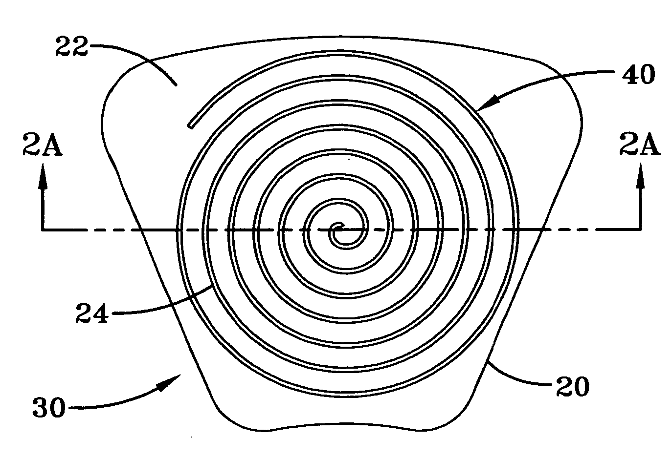
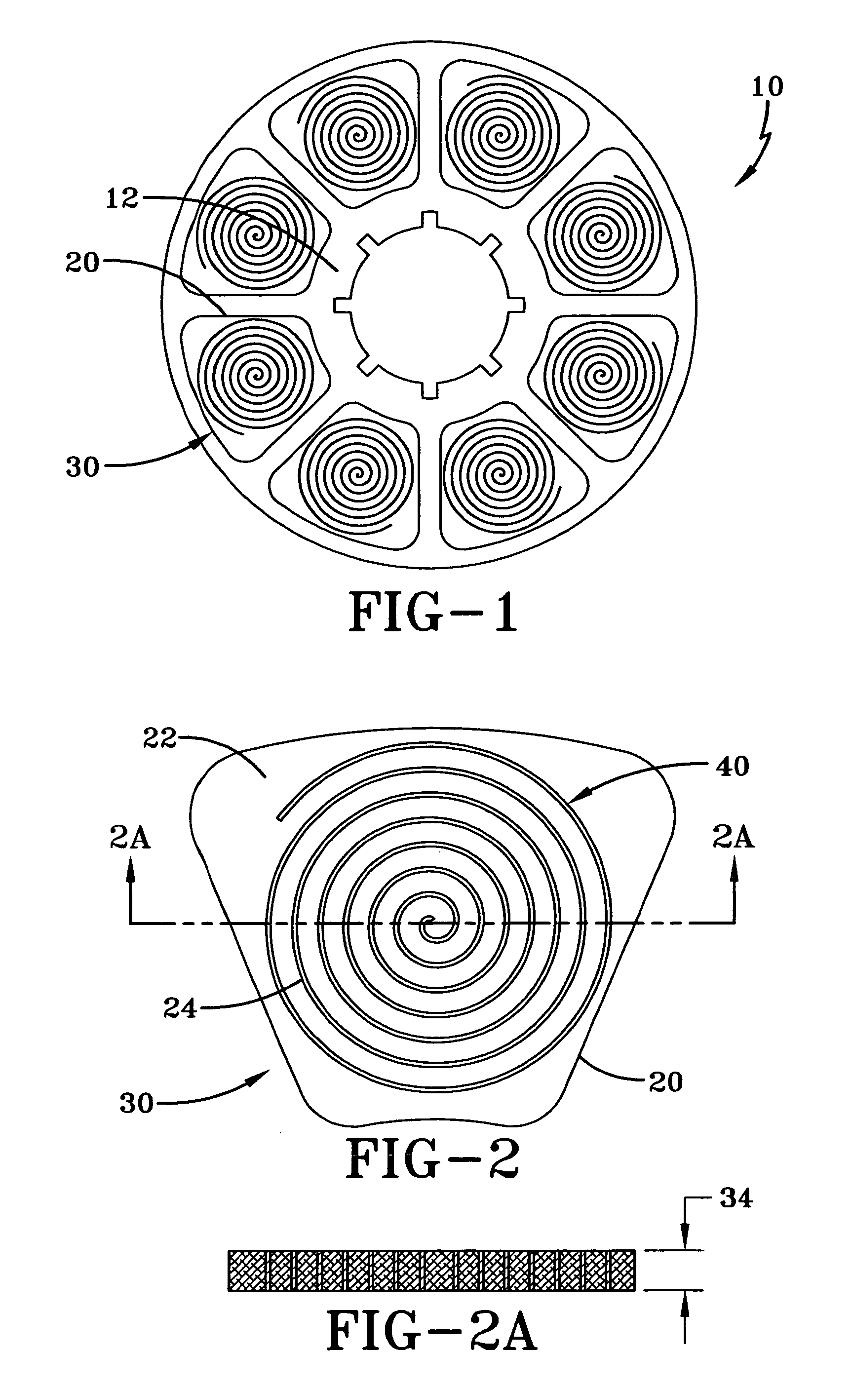
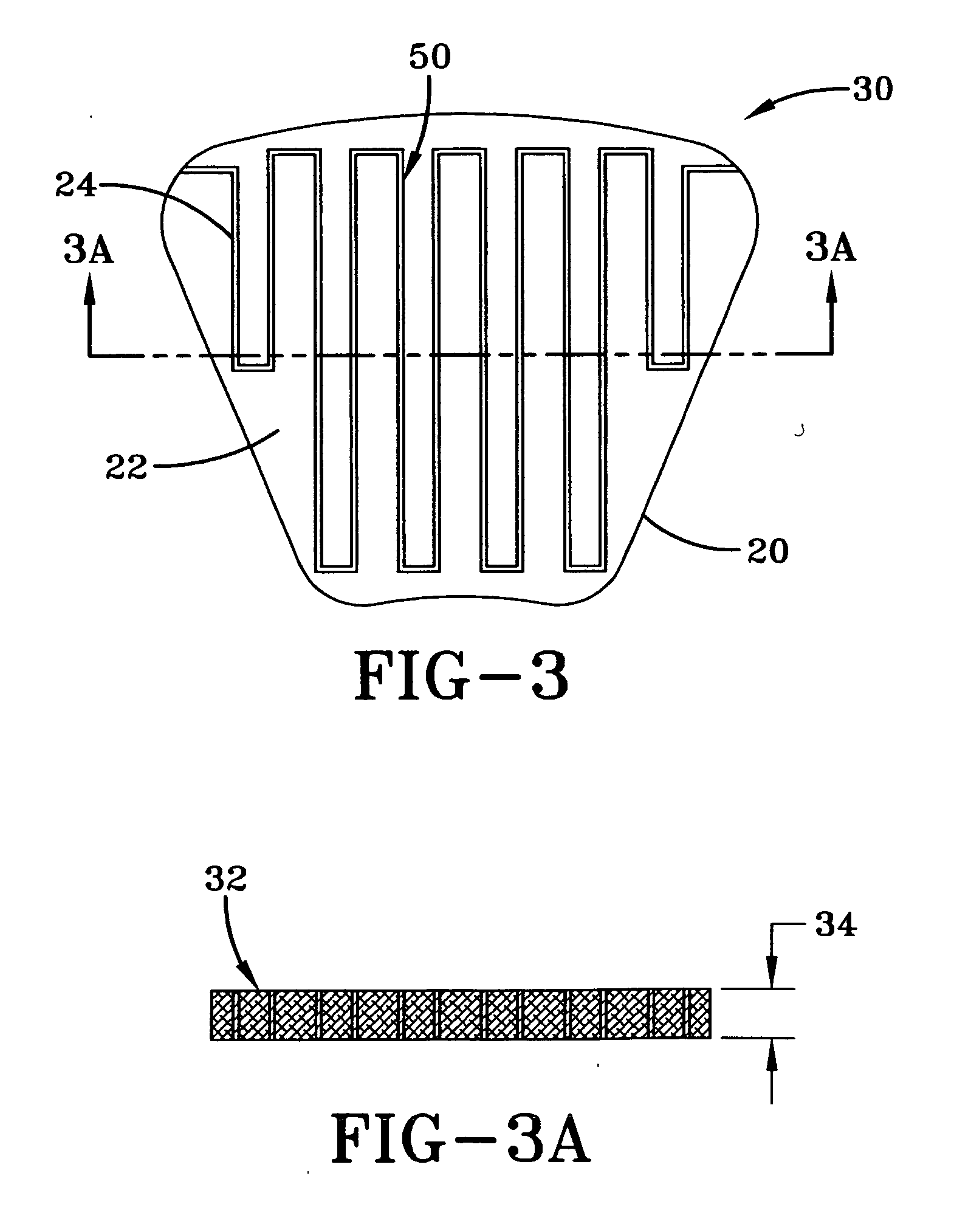
[0015] Various aspects of the invention are presented in FIGS. 1-6 which are not drawn to scale and in which like components are numbered alike. Referring now to FIGS. 1-3, according to an aspect of the invention, a brake disk 10 has an annular disc 12, and a plurality of segmented brake lining cups 20 secured to the disc 10. These lining cups 20 are filled with brake lining material 22, forming a brake lining assembly 30. The brake lining assembly 30 has a wear surface 32. This is a fairly standard brake disk construction. The present invention improves this construction by reinforcing the brake lining material 22 with a metallic winding structure 24.

[0016] Prior art has reinforced the brake lining with grids, or honeycomb structures. These methods require assembly and bonding technologies to fasten the individual pieces together. Bond techniques for metallic reinforcements typically include brazing or welding. As a result, there is an overlap of material at the bond interface. Th...


PUM

PropertyMeasurementUnit
widthaaaaaaaaaa
thermal conductivityaaaaaaaaaa
metallicaaaaaaaaaa

Abstract

A method of producing a brake lining assembly having a wear surface with increased wear characteristics comprises the steps of winding a metal strip, placing the wound metal strip into a brake lining cup, filling the brake lining cup with a brake lining material of powdered metal and then sintering the powdered metal thus embedding the wound metal strip into the brake lining material, forming a brake lining assembly. The metal strip has a width approximately equal to that of the brake lining assembly desired depth, and is wound into a shape and size which will fit into the brake lining cup. The wound metal strip is then placed into the brake lining cup such that the metal strip width is approximately perpendicular to the brake lining wear surface. Alternatively the wound metal strip may be produced by extrusion. The result is a brake lining assembly which is reinforced by a metallic winding structure.

Description

BACKGROUND [0001] The present invention is in the field of braking systems. More specifically this invention relates to the brake linings for use in a braking disc. [0002] Modern steel brake designs rely on the friction generated between solid steel and sintered metal wear surfaces. The steel surface may take the form of a full annular disc, or may be segmented and connected, with or without a substructure, to form a full annular disc. The sintered metal components are lower in strength, and therefore require a different method of assembly than the steel components. [0003] Modern steel aircraft brakes are typically created by adding powdered metal to formed cups, and then sintering this powdered metal to fuse it to the cups. Brake linings have been shown to wear less when surface temperatures are kept low. Unfortunately, powdered metal compounds act as good insulators, thereby retaining surface heat, which causes increased wear. [0004] Prior methods of brake pad reinforcement have p...

Claims


Application Information

Patent Timeline
Patent Type & Authority Applications(United States)
IPC IPC(8): F16D69/00
CPCF16D69/00F16D2069/002F16D2069/0441
Inventor THORP, JOHN H. E.
Owner THE BF GOODRICH CO
Why Eureka
Try Eureka