Tip assembly having at least three components for hot runner nozzle

a technology of hot runner and component, which is applied in the field of injection molding apparatus, can solve problems such as preventing heat transfer from a heater

Inactive Publication Date: 2005-07-26
MOLD MASTERS 2007
View PDF81 Cites 36 Cited by
  • Summary
  • Abstract
  • Description
  • Claims
  • Application Information

AI Technical Summary

Problems solved by technology

A problem with such nozzle constructions, however, is that the tip surrounding piece, which has a lower thermally conductive material than the tip, can impede heat transfer from a heater on the nozzle, to melt that is in the tip.

Method used


Image

  • Tip assembly having at least three components for hot runner nozzle
  • Tip assembly having at least three components for hot runner nozzle
  • Tip assembly having at least three components for hot runner nozzle

Examples


first embodiment

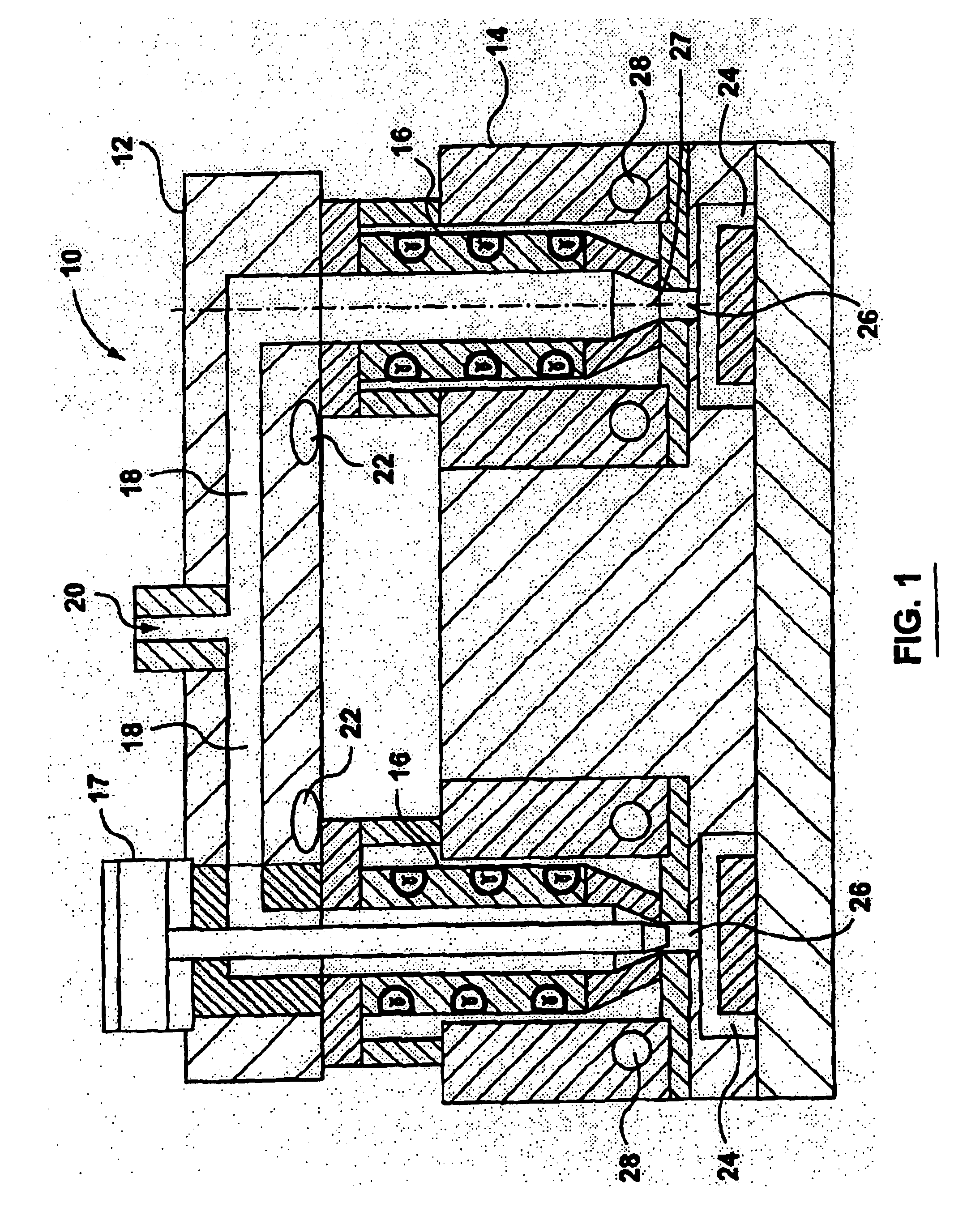
[0025]Reference is made to FIG. 1, which shows an injection molding apparatus 10, which includes a runner component 12, a mold component 14, a plurality of nozzles 16 in accordance with the present invention and a plurality of optional valve pin devices 17.

[0026]The runner component 12 includes a plurality of runners 18, which transfer melt from a main runner inlet 20 to the nozzles 16. The runner component 12 may be heated by a heater 22.

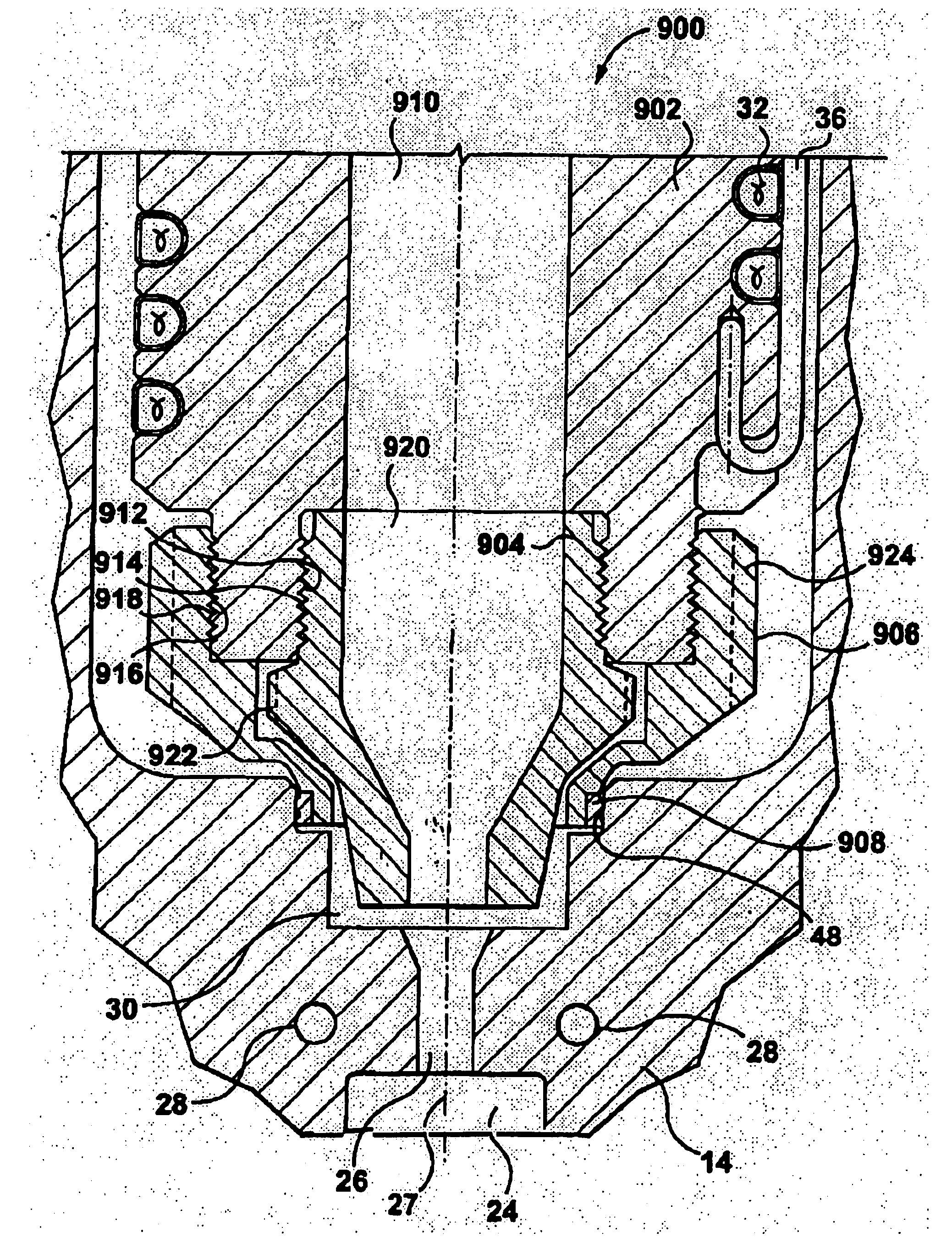
[0027]The mold component 14 is made up of a plurality of mold components, which together define a plurality of mold cavities 24. A gate 26 into each mold cavity 24 is defined in the mold component 14 and has an axis 27. Each gate 26 is positioned downstream from one of the nozzles 16.

[0028]A plurality of cooling channels 28 may be included in the mold component 14. The cooling channels 28 transport a cooling fluid throughout the mold component 14 to cool and solidify melt in the mold cavities 24.

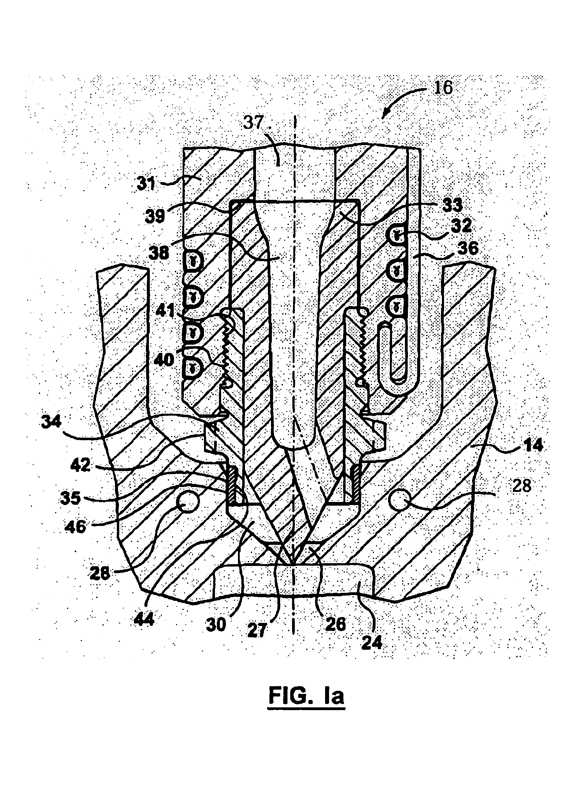
[0029]Reference is made to FIG. 1a. Each nozzle 14 re...

second embodiment

[0046]Reference is made to FIG. 2, which shows a nozzle 100 in accordance with the present invention, in combination with mold component 14. The nozzle 100 may be similar to the nozzle 16 (FIG. 1a), includes the nozzle body 31, the heater 32, a tip 102, the tip surrounding piece 34 and the mold component contacting piece 35. The tip 102 differs from the tip 33 in that the tip 102 has a melt passage 104 with an exit 106 that is concentric about the axis 27 of the gate 26.

[0047]Thus, a nozzle in accordance with the present invention may have a tip that inserts into the gate 26 and has an off-centre melt passage exit (as shown in FIG. 1a), or alternatively the nozzle may a tip that has a melt passage exit that is concentric about the axis 27 of the gate 26 (as shown in FIG. 2).

third embodiment

[0048]Reference is made to FIG. 3, while shows a nozzle 200 in accordance with the present invention, in combination with mold component 14. The nozzle 200 may be similar to any of the nozzles described herein, such as the nozzle 100 (FIG. 2). The nozzle 200 includes the nozzle body 31, the heater 34, a two-component tip 202, the tip surrounding piece 34 and the mold component contacting piece 35. The tip 202 may be similar to the tip 102 (FIG. 2) and may define a tip melt passage 203 which is in fluid communication with the body melt passage 37. The tip 202, however, includes an inner portion 204 and an outer portion 206. The inner portion 204 contains the melt passage 102 therethrough. The inner portion 204 may be made from a wear resistant, thermally conductive material. For example, the inner portion 204 may be made from Tungsten Carbide. The outer portion 206 may be made from a thermally conductive material, but may be made from a material that is less wear resistant than the m...


PUM

PropertyMeasurementUnit
meltaaaaaaaaaa
thermally conductiveaaaaaaaaaa
thermal conductivityaaaaaaaaaa

Abstract

A nozzle for an injection molding apparatus is provided. The injection molding apparatus has a mold component that defines a mold cavity and a gate into the mold cavity. The nozzle includes a nozzle body, a heater, a tip, a tip surrounding piece and a mold component contacting piece. The nozzle body defines a nozzle body melt passage therethrough, that is adapted to receive melt from a melt source. The heater is thermally connected to the nozzle body for heating melt in the nozzle body. The tip defines a tip melt passage therethrough, that is downstream from the nozzle body melt passage, and that is adapted to be upstream from the gate. The tip surrounding piece is removably connected with respect to said nozzle body. The mold component contacting piece is connected with respect to the nozzle body. The material of the mold component contacting piece has a thermal conductivity that is less than at least one of the thermal conductivity of the material of the tip and the thermal conductivity of the material of the tip surrounding piece.

Description

CROSS-REFERENCE TO RELATED APPLICATIONS[0001]This application claims the benefit of U.S. Provisional Application No. 60 / 330,540, filed Oct. 24, 2001, U.S. Provisional Application No. 60 / 346,632, filed Jan. 10, 2002, and U.S. Provisional Application No. 60 / 356,170, filed Feb. 14, 2002.FIELD OF THE INVENTION[0002]This invention relates to an injection molding apparatus, and more particularly to a tip assembly having at least three components for a nozzle for an injection molding apparatus.BACKGROUND OF THE INVENTION[0003]It is known for a nozzle in hot runner injection molding apparatus to include a thermally conductive body and a thermally conductive tip. Furthermore, it is known for the nozzle to include a separate piece that joins to the nozzle body and retains the tip in place in the nozzle body. The tip surrounding piece is also typically used to form a seal surrounding the space between the nozzle and the mold component to which the nozzle transfers melt. Because the mold compon...

Claims


Application Information

Patent Timeline
Patent Type & Authority Patents(United States)
IPC IPC(8): B29C45/74B29C45/20B29C45/72B29C47/12B29C45/27B29C48/30
CPCB29C45/278B29C2045/2761
Inventor OLARU, GEORGE
Owner MOLD MASTERS 2007
Why Eureka
Try Eureka