
Non-round filler rods and tubes with superabsorbent water swellable material for large cables

a technology of superabsorbent water swelling material and filler rod, which is applied in the direction of optics, fibre mechanical structures, instruments, etc., can solve the problems of insufficient amount of water swelling material used to properly protect optical fibers, relatively large gaps between buffer tubes, etc., and achieves the effect of increasing the effectiveness and speed of gap plugging and maximizing the amount of water swelling material

Inactive Publication Date: 2005-07-26
DRAKA COMTEQ BV
View PDF19 Cites 8 Cited by
  • Summary
  • Abstract
  • Description
  • Claims
  • Application Information

AI Technical Summary

Benefits of technology

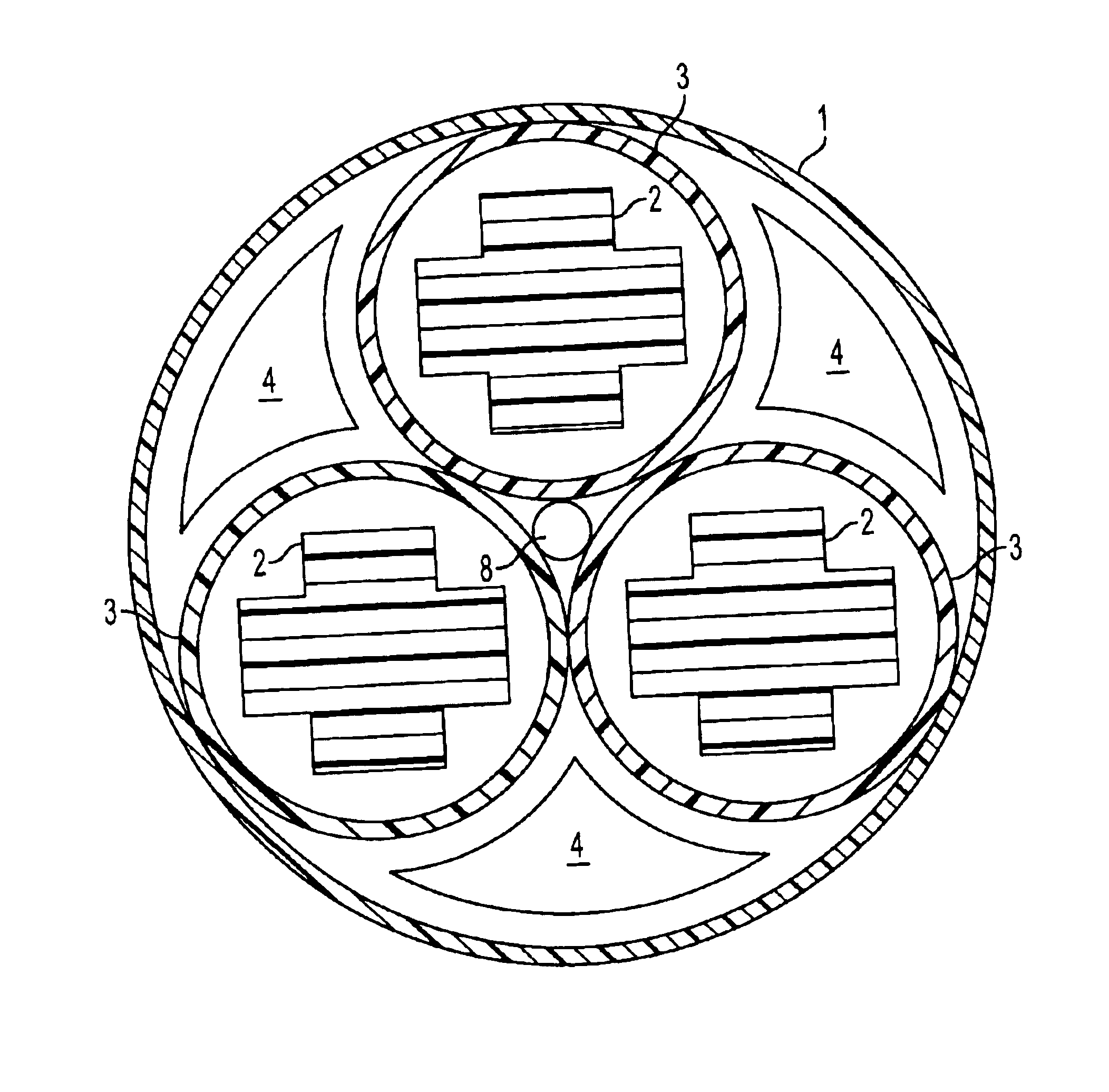
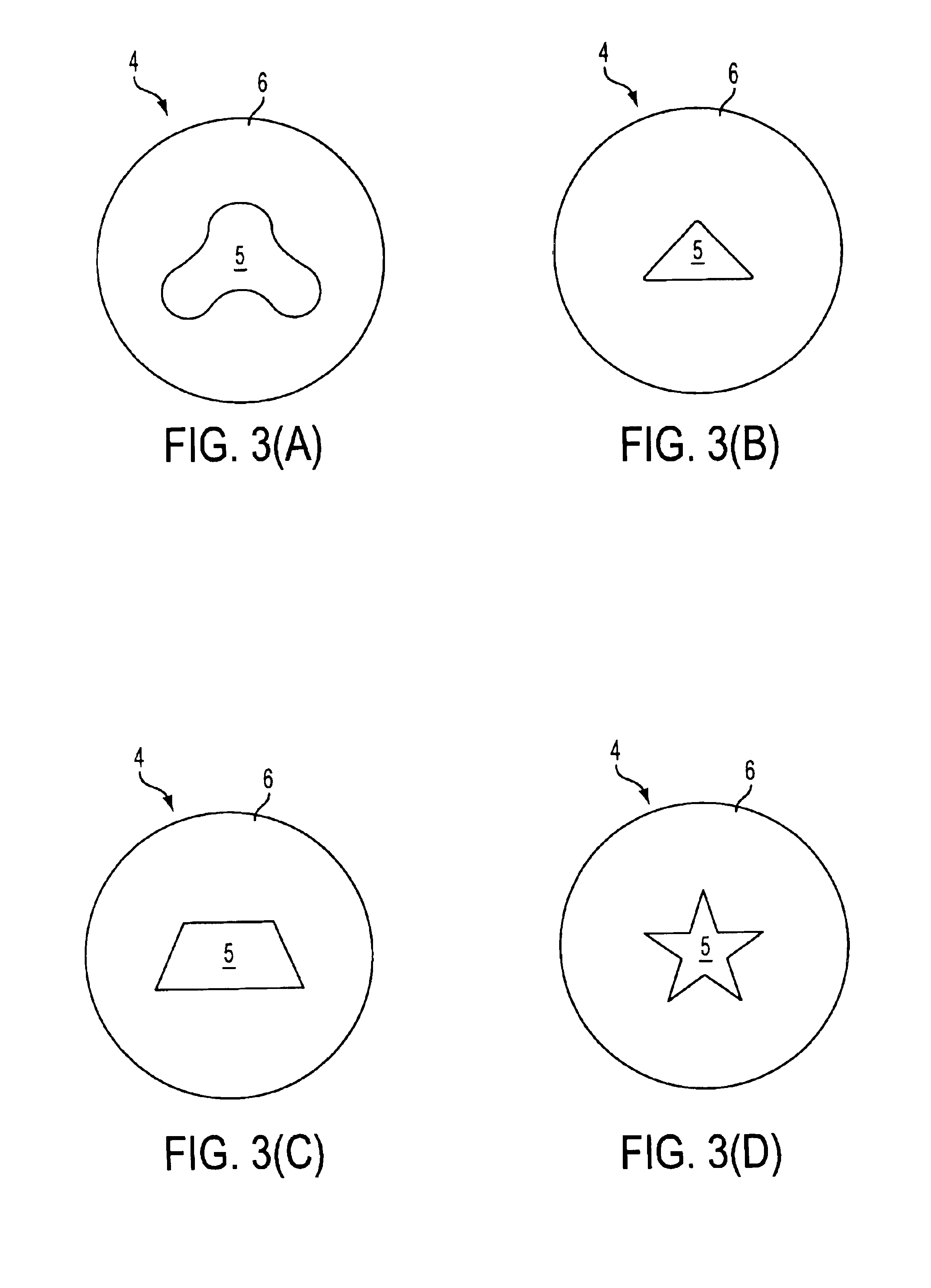
[0005]To provide greater protection from water penetration, novel filler tubes and rods are disclosed. Throughout the remainder of the specification, the term filler rod will be used for the tube of convenience. However the term filler rod as so used is meant to encompass one or more filler rods, filler tubes, or equivalent structure. The filler rod maximizes the amount of water swellable material while also maximizing the surface area of the core of the filler rod which serves as a substrate for the water swellable material. Additionally, the cross-sectional shape of the filler rod can be designed to match the cross-sectional shape of the interstitial gaps found in the cable between the buffer tubes 3 and the cable outer jacket 1.
[0007]Another design is a filler rod which does not have a core but instead is made entirely out of a suberabsorbant water swellable material. In this manner, no core is required and the amount of water swellable material is maximized. Increasing the amount of water swellable material also increases the effectiveness and speed of gap plugging. Additionally, this type of filler rod can also be shaped to match the cross-sectional shape of the interstitial gaps found in the cable between the buffer tubes 3 and the cable outer jacket 1. With the interstitial gaps filled, the cable is afforded its greatest protection against water penetration.

Problems solved by technology

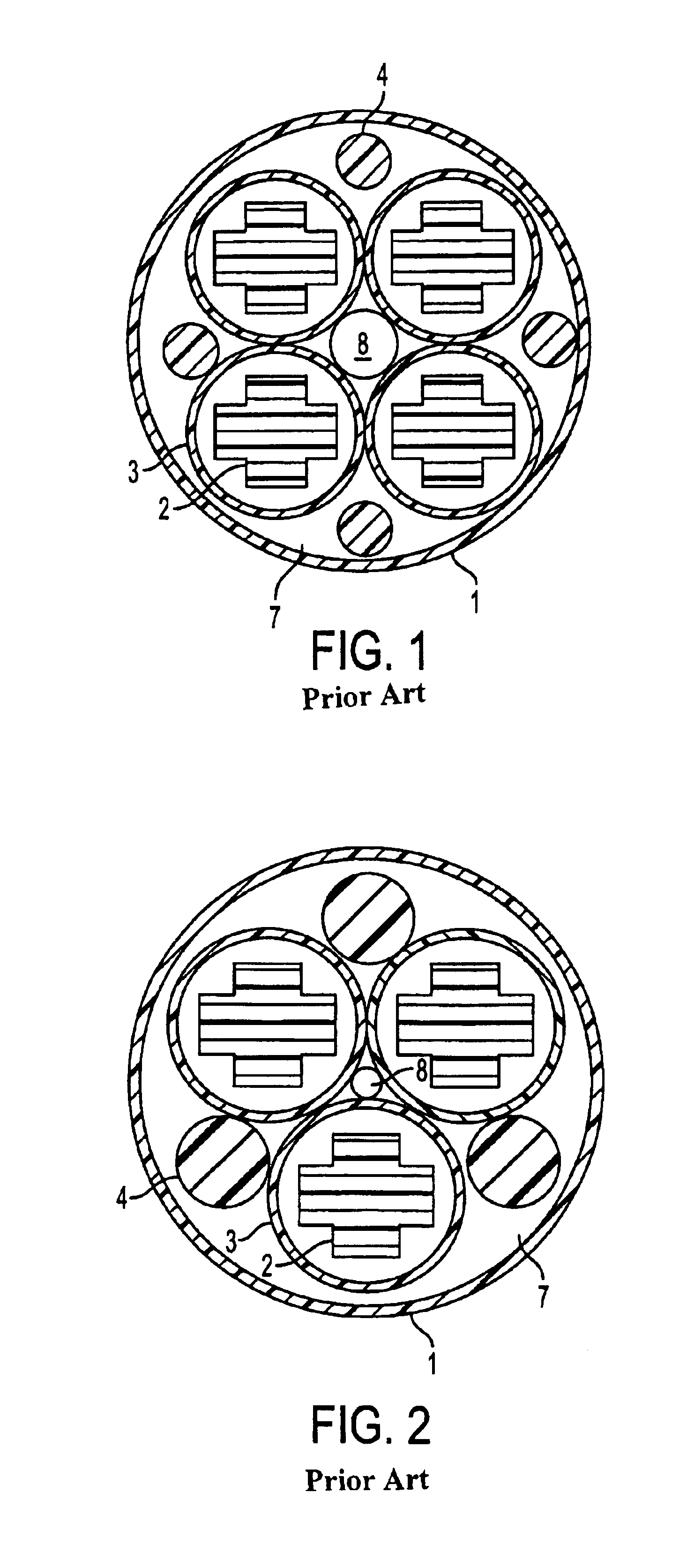
However, using a lower number of larger buffer tubes 3 produces relatively large gaps between the buffer tubes 3 and the interior surface of the cable outer jacket 1.
These large gaps create a problem by allowing for water penetration along the length of the cable.
While use of such filler rods 4 help close the interstitial gaps and to prevent water penetration along the cable, the amount of water swellable material now used is insufficient to plug the gaps or to properly protect the optical fibers, especially in the case of larger diameter cables with larger interstitial gaps.

Method used


Image

  • Non-round filler rods and tubes with superabsorbent water swellable material for large cables
  • Non-round filler rods and tubes with superabsorbent water swellable material for large cables
  • Non-round filler rods and tubes with superabsorbent water swellable material for large cables

Examples


Embodiment Construction

[0021]Hereinafter, embodiments of the present invention will be described in detail with reference to the attached drawings. The present invention is not restricted to the following embodiments, and many variations are possible within the spirit and scope of the present invention. The embodiments of the present invention are provided in order to more completely explain the present invention to one skilled in the art.

[0022]Referring to FIGS. 1-5, a fiber optic cable having at least one novel filler rod or tube will now be described. The fiber optic cable is comprised of a plurality of buffer tubes 3, each of which contains a plurality of optical fibers. In larger cables, the number of optical fibers can reach around 864 to 1728. The buffer tubes 3 are generally round in cross-section. The buffer tubes 3 are disposed adjacent to one another within the cable outer jacket 1, although the buffer tubes 3 do not have to contact each other. However, in order to maximize the number of buffer...


PUM


Abstract

A fiber optic cable having a plurality of buffer tubes and filler rods or filler tubes disposed between the inner surface of the outer jacket of the fiber optic cable and the buffer tubes. The buffer tubes contain a plurality of optical fibers. The filler rods have a non-round core surrounded by a superabsorbant water swellable coating to provide protection for the optical fibers against the penetration of water within the cable. The filler rods and filler tubes are made of a solid or porous or foam-type material expanding in the presence of water.

Description

BACKGROUND OF THE INVENTION[0001]The present invention relates generally to filler rods for fiber optic cables, and more specifically to non-round filler rods containing an increased amount of superabsorbent water swellable material for large-diameter fiber optic cables.[0002]Fiber optic cables have been used by the telecommunications industry for a number of years to transmit information at very high rates over long distances. Fiber optic cables come in a variety of configurations, including: cables with a centrally positioned single buffer tube containing one or more optical fibers; cables with a plurality of buffer tubes stranded in a helical or alternating helical arrangement about a central strength member; and cables with slotted cores in which a plurality of optical fibers reside.[0003]The cables in metropolitan areas are expected to accommodate large numbers of fibers per cable. In particular, the fiber optic ribbon cables containing 864 and 1728 fibers are installed in 1.5 ...

Claims


Application Information

Patent Timeline
IPC IPC(8): G02B6/44
CPCG02B6/4494G02B6/4411G02B6/44384
Inventor NECHITAILO, NICHOLAS V.
Owner DRAKA COMTEQ BV
Learn More