Mobile telephone system configured to confirm receiver speed conditions

a mobile telephone system and speed condition technology, applied in the field of telephone systems, can solve problems such as the inability to conduct the conversation as soon as possible in an emergency cas

Inactive Publication Date: 2005-07-26
MITSUBISHI ELECTRIC CORP
View PDF11 Cites 70 Cited by
  • Summary
  • Abstract
  • Description
  • Claims
  • Application Information

AI Technical Summary

Benefits of technology

[0027]Due to this arrangement, there is obtained such an effect that the starting of

Problems solved by technology

Since the conventional telephone system is arranged as described above, there is such a problem that despite the state in which the telephone sys

Method used


Image

  • Mobile telephone system configured to confirm receiver speed conditions
  • Mobile telephone system configured to confirm receiver speed conditions
  • Mobile telephone system configured to confirm receiver speed conditions

Examples


first embodiment

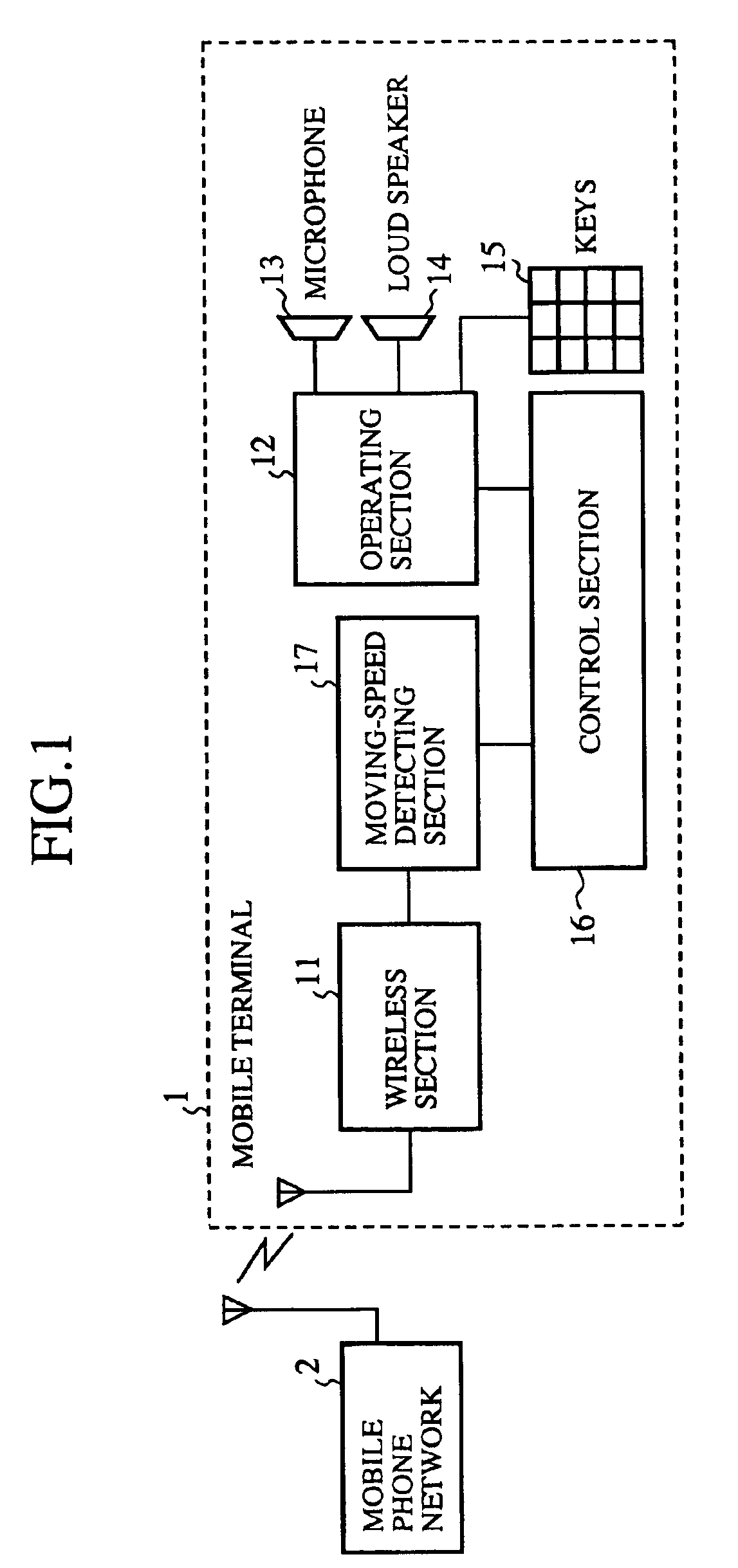
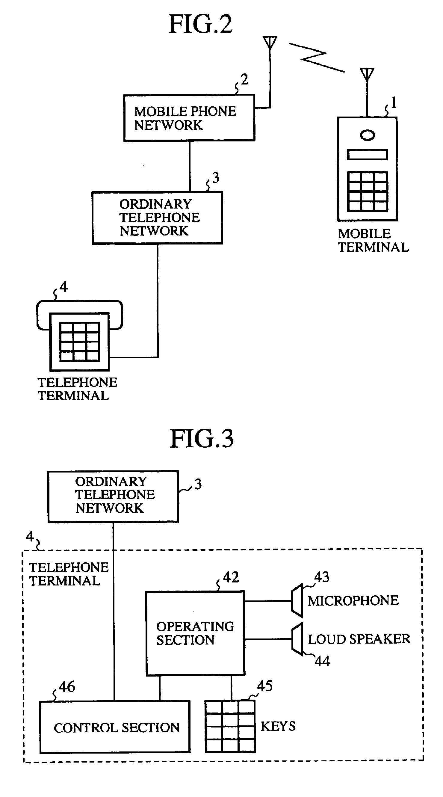
[0035]FIG. 2 is a block diagram showing an arrangement of a telephone system according to a first embodiment of this invention. In the figure, reference numeral 1 denotes a mobile terminal, reference numeral 2 denotes a mobile phone network for making a communication with the mobile terminal, reference numeral 3 denotes an ordinary telephone network, and reference numeral 4 denotes a telephone terminal which is connected to the ordinary telephone network 3. The mobile terminal 1 has the same arrangement as that of the conventional one as shown in FIG. 1 and is provided with a moving-speed detector section 17. It is to be understood that the mobile phone network 2 includes: base stations for directly transmitting to and receiving from the mobile terminal 1; a mobile telephone switching station for performing interconnecting services with the base station; and a gate mobile telephone central station for performing interconnection with the ordinary telephone network 3.

[0036]FIG. 3 is a...

second embodiment

[0052]The arrangement of the telephone system according to a second embodiment is the same as that shown in FIG. 2 of the first embodiment. The arrangement of the mobile terminal 1 is the same as that of the conventional one shown in FIG. 1, and the arrangement of the telephone terminal 4 is the same as that shown in FIG. 3 of the first embodiment.

[0053]A description will now be made about the operation.

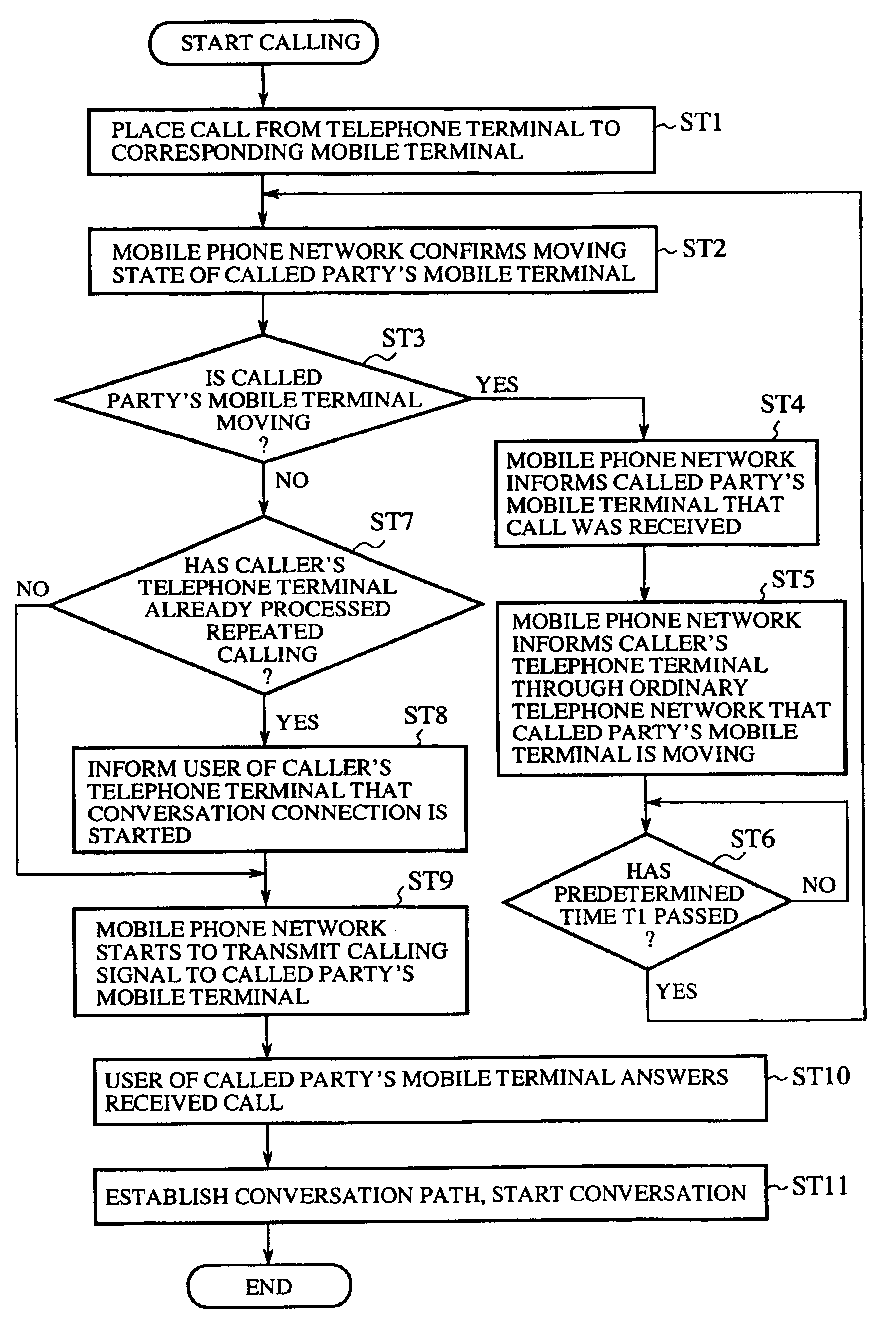
[0054]FIG. 5 is a flow chart showing the flow of processing in the telephone system according to the second embodiment of this invention. The processing from step ST1 through step ST4 is the same as that shown in FIG. 4 of the first embodiment. In this embodiment, after the processing in step ST4, the mobile phone network 2 waits in step ST21 for a predetermined period of time T1. Thereafter, the process proceeds to step ST2 to thereby confirm the moving state of the called party's mobile terminal 1 once again.

[0055]Then, in step ST3, if the called party's mobile terminal 1 is found ...

third embodiment

[0061]The arrangement of the telephone system according to a third embodiment is the same an that shown in FIG. 2 of the first embodiment, and the arrangement of the telephone terminal 4 is the same as that shown in FIG. 3 of the first embodiment.

[0062]FIG. 6 is a block diagram showing an arrangement of the called party's mobile terminal 1 and the mobile phone network 2 according to the third embodiment. In the above-described first embodiment and second embodiment, the mobile terminal 1 is provided with the moving-speed detector 17. In this embodiment, on the other hand, the mobile phone network 2 is provided with a moving-speed detector 31 for detecting the moving speed of each of the mobile terminals 1.

[0063]A description will now be made about the operation.

[0064]The flow chart showing the flow of processing the telephone system according to the third embodiment is the same as that shown in FIG. 4 of the first embodiment or that shown in FIG. 5 of the second embodiment. Basicall...


PUM


Abstract

In response to a call from a telephone terminal (4) to a mobile terminal (1), a mobile phone network (2) confirms the moving state of the mobile terminal (1). If the mobile terminal (1) is found to be moving, the mobile phone network (2) notifies the mobile terminal (1) of the fact that a call was received by the mobile terminal (1) and also notifies the caller's telephone terminal (4) of the fact that the called party's mobile terminal (1) is moving, and causes the caller's terminal (1) to call again after the lapse of a predetermined time. If the called party's terminal (1) is found to be not moving, the mobile phone network (2) transmits a calling signal to the mobile terminal (1).

Description

TECHNICAL FIELD[0001]This invention relates to a telephone system which is provided with a mobile terminal and a mobile phone network.BACKGROUND ART[0002]FIG. 1 is a block diagram showing an arrangement of a telephone system as disclosed in Japanese Patent Application Laid-Open No. 98575 / 1999. In the figure, reference numeral 1 denotes a mobile terminal, and reference numeral 2 denotes a mobile phone network inclusive of a base station or the like which performs transmission and reception of radio signals to and from the mobile terminal 1.[0003]In the mobile terminal 1, reference numeral 11 denotes a wireless section for performing transmission and reception of radio signals to and from the mobile phone network 2. Reference numeral 12 denotes an operating section for processing inputs from a microphone 13, outputs to a loud speaker 14, and inputs from keys 15 for entering various setting inputs. Reference numeral 16 denotes a control section that controls transmission and reception ...

Claims


Application Information

Patent Timeline
IPC IPC(8): H04M1/2745H04M1/60H04M1/663H04M3/436H04M3/48H04W4/16
CPCH04M1/6041H04M1/663H04W4/16
Inventor KINOSHITA, KATSUMI
Owner MITSUBISHI ELECTRIC CORP
Why Eureka
Try Eureka