
Air intake system for multi-cylinder engine

a multi-cylinder engine and air intake technology, applied in the direction of engine starters, combustion-air/fuel-air treatment, machines/engines, etc., can solve the problems of difficult layout of the intake system and considerably complex structure, and achieve the effect of improving the inertia effect of the intake flow

Inactive Publication Date: 2005-08-02
MAZDA MOTOR CORP
View PDF7 Cites 5 Cited by
  • Summary
  • Abstract
  • Description
  • Claims
  • Application Information

AI Technical Summary

Benefits of technology

[0005]In view of the aspect above, an object of the present invention is to provide a simple intake system for a multi-cylinder engine which improves the inertia effect of the intake flow and acceleration response at once.

Problems solved by technology

This causes problems such as a considerably complex structure with difficulty in the layout of the intake system.

Method used


Image

  • Air intake system for multi-cylinder engine
  • Air intake system for multi-cylinder engine
  • Air intake system for multi-cylinder engine

Examples


Embodiment Construction

[0031]Preferred embodiments of the present invention will be described with reference to the accompanying drawings.

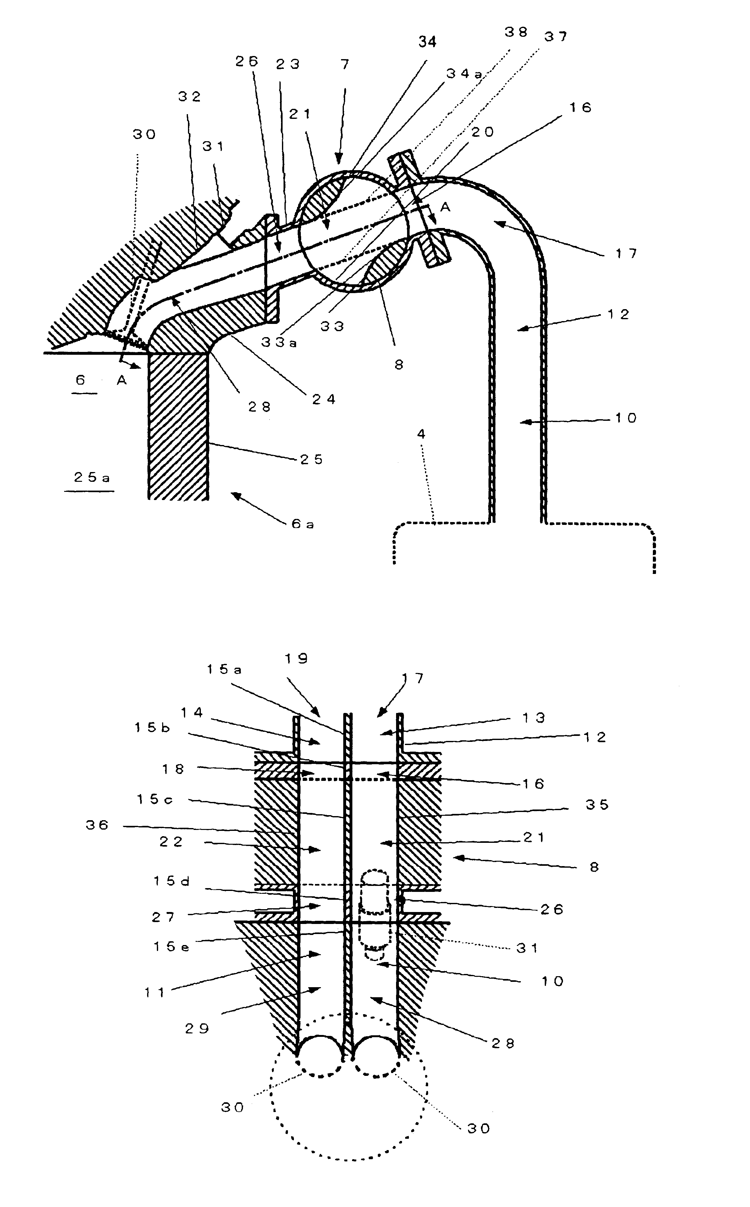
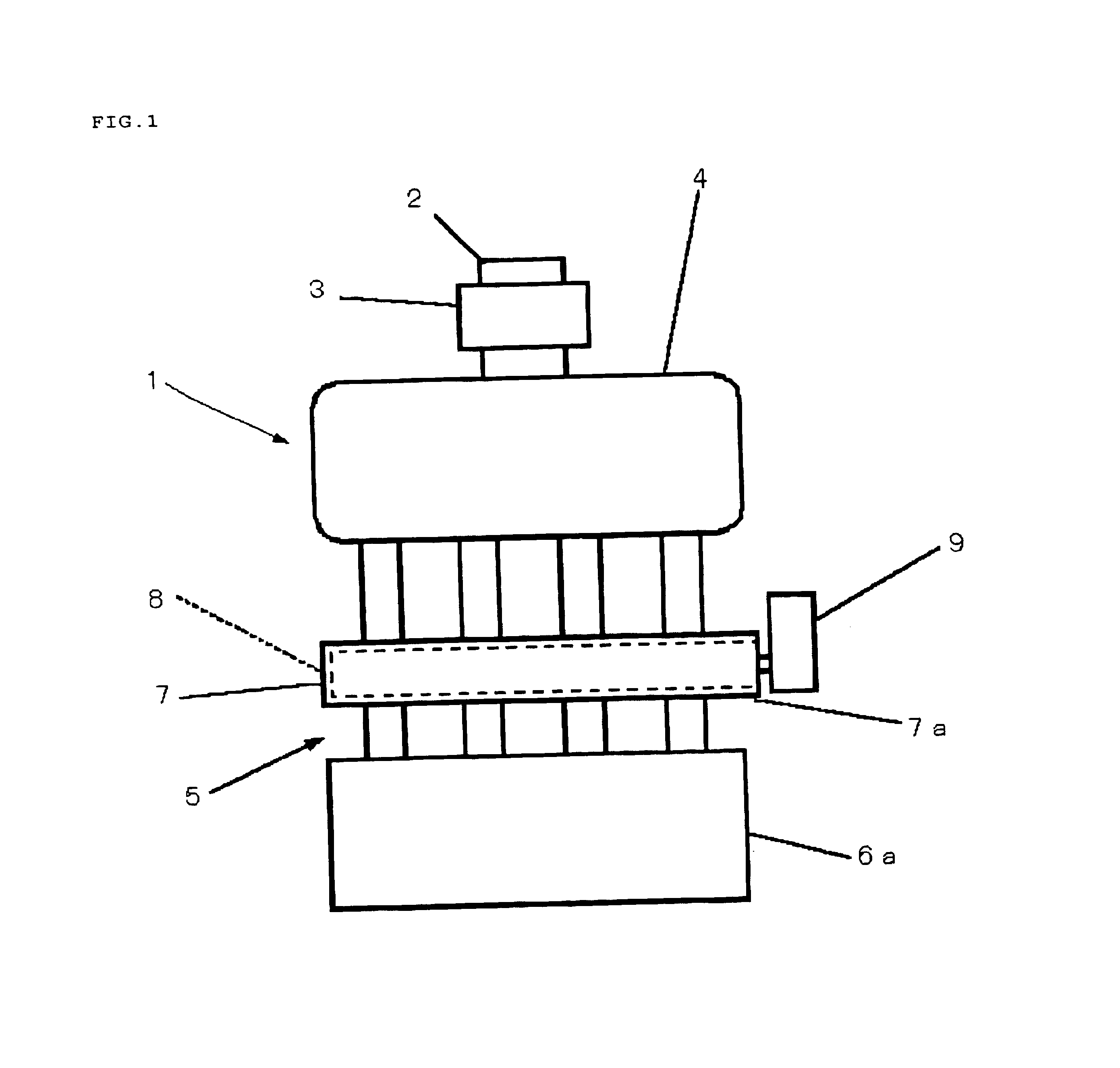
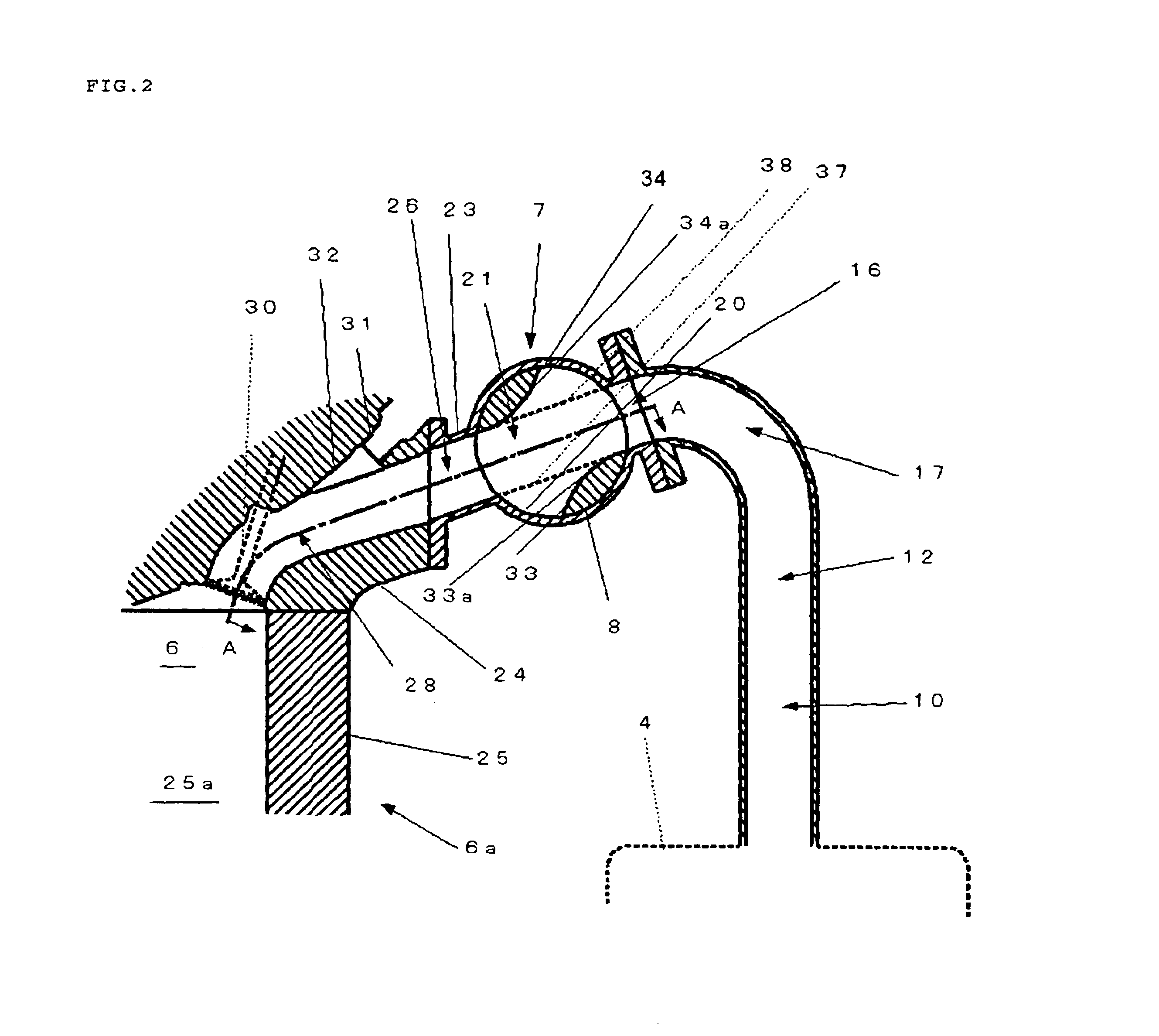
[0032]FIG. 1 to FIG. 11 illustrate an intake system of a four-cylinder engine. FIG. 1 illustrates an overall configuration of the four-cylinder internal combustion engine. An intake system 1 is provided with a duct 2 for introducing the intake air from atmosphere, an air cleaner 3 communicating (e.g., connected) with the duct 2 in order to remove dust from the intake air, a surge tank 4 for introducing the intake air from the air cleaner 3 so that the intake air does not pass through the throttle valve, and individual intake passages 5 formed corresponding to each cylinder so as to supply the intake air from the surge tank 4 to each combustion chamber of an engine body 6a. A rotary-type throttle valve device 7 is provided for each of the individual intake passage 5 at a midway portion between the surge tank 4 and the combustion chamber 6 (shown in FIG. 2). The valve dev...


PUM


Abstract

A throttle device is arranged in the midstream of an individual passage consisting of a low-speed individual intake passage and a high-speed individual intake passage on the downstream of a surge tank. A valve body is rotatably provided in the throttle valve device. The inside of the valve body is formed with an in-valve low-speed passage and an in-valve high-speed passage that are adjacently placed with respect to the rotational axis of the valve body. The intake air supply is performed through only the low-speed individual passage when the opening of the valve body is equal to or less than a predetermined value, and through both the low-speed individual intake passage and high-speed individual intake passage when the opening of the body is larger than the predetermined value.

Description

TECHNICAL FIELD OF THE INVENTION[0001]The present invention relates to an intake system of a multi-cylinder engine.BACKGROUND OF THE INVENTION[0002]Conventionally, a so-called multi-throttle valve is known in which throttle valves are disposed in individual intake passages for each cylinder of an engine. The multi-throttle valve linearly adjusts the amount of intake air according to driver's demand for example, thereby improving acceleration response. Moreover, a rotary-type throttle valve is known in which its valve body has a rotatable and cylindrical shape and is formed with an intake passage therein, while being located closely to a combustion chamber in an intake passage. (refer to Japanese publication of patent application no. 2001-73813) This throttle valve should be located as closely as possible to the engine, on the downstream side of the intake passage, for further improvement in acceleration response, because this arrangement reduces the volume of the portion of the inta...

Claims


Application Information

Patent Timeline
Patent Type & Authority Patents(United States)
IPC IPC(8): F02B31/00F02B27/02F02D9/16F02B31/08F02D9/08F02D9/02F02M35/104F02M35/108
CPCF02B27/0284F02B31/085F02D9/16Y02T10/146F02B27/0289Y02T10/12
Inventor IWATA, NORIYUKIHIRASHITA, SHIGEYUKIYOHSO, TAKASHIFUJIKAWA, TATSUYA
Owner MAZDA MOTOR CORP
Learn More