Nasal mask

a mask and nasal tube technology, applied in the field of nasal masks, can solve problems such as patient discomfor

Inactive Publication Date: 2005-08-02
FISHER & PAYKEL HEALTHCARE LTD
View PDF17 Cites 75 Cited by
  • Summary
  • Abstract
  • Description
  • Claims
  • Application Information

AI Technical Summary

Benefits of technology

[0004]It is an object of the present invention to attempt to provide a patient interface which goes some way to over...

Problems solved by technology

In the typical values of pressure in CPAP treatment, usually between 4 cm H2O to 20 cm H2O, prior art attempts at...

Method used


Image

  • Nasal mask
  • Nasal mask
  • Nasal mask

Examples


Embodiment Construction

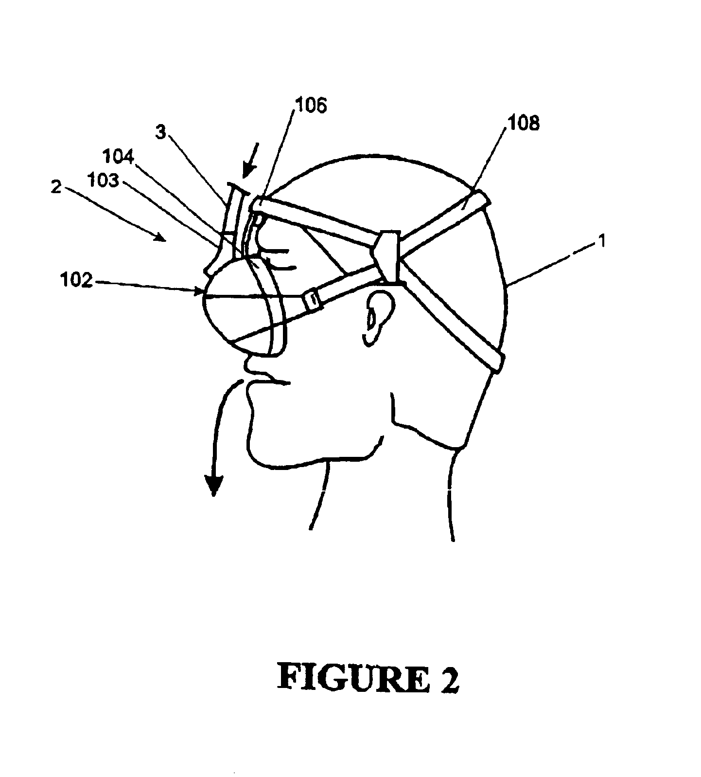
[0045]The present invention provides improvements in the delivery of CPAP therapy. In particular a patient interface is described which is quieter for the user to wear and reduces the side leakage as compared with the prior art. It will be appreciated that the patient interface as described in the preferred embodiment of the present invention can be used in respiratory care generally or with a ventilator but will now be described below with reference to use in a humidified CPAP system. It will also be appreciated that the present invention can be applied to any form of patient interface including, but not limited to, nasal masks and mouthpieces.

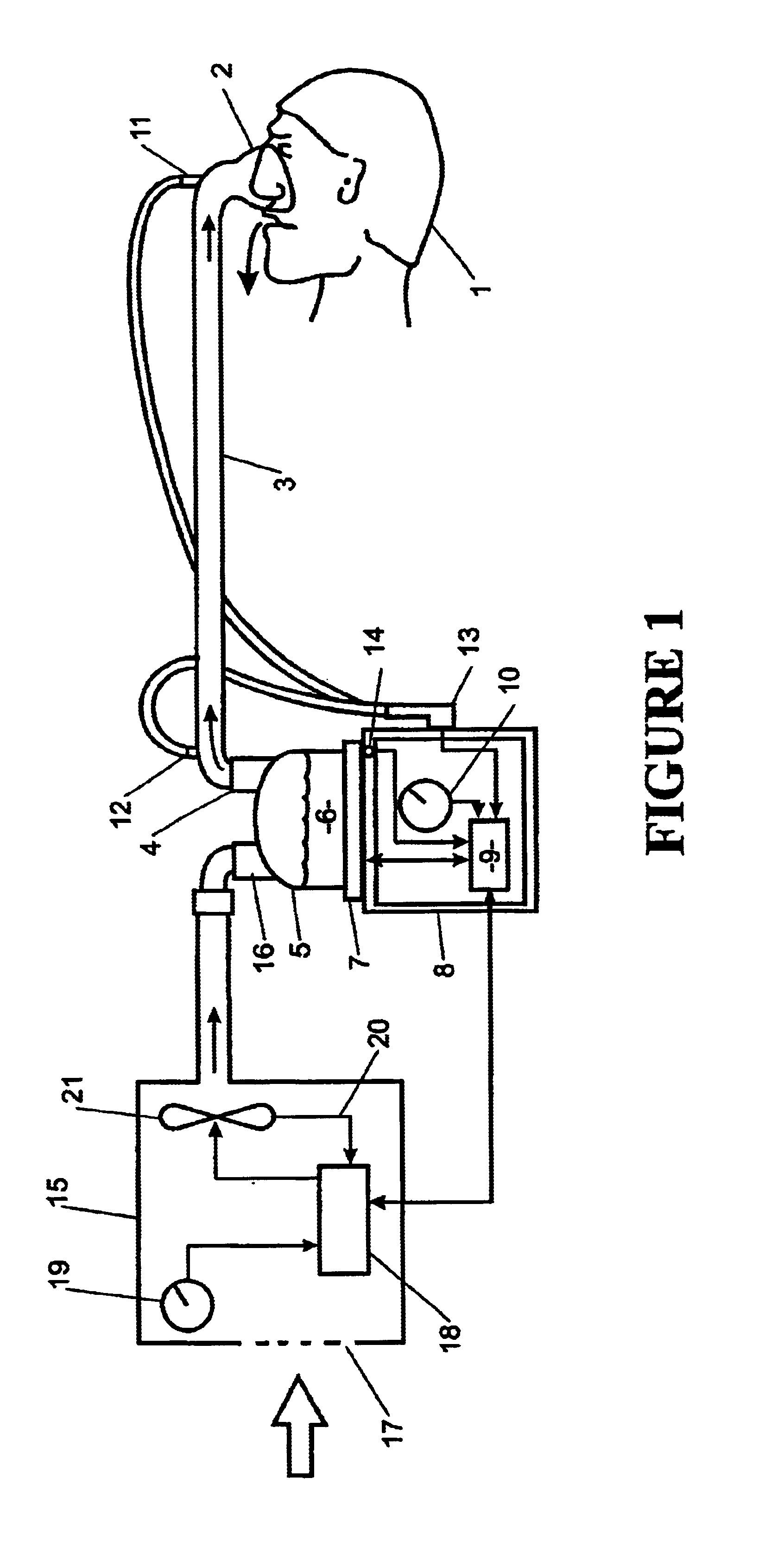
[0046]With reference to FIG. 1 a humidified Continuous Positive Airway Pressure (CPAP) system is shown in which a patient 1 is receiving humidified and pressurised gases through a patient interface 2 connected to a humidified gases transportation pathway or inspiratory conduit 3. It should be understood that delivery systems could also be VPA...


PUM


Abstract

A system is disclosed comprising a high pressure gases source: for example a compressor, a low cross section conduit adapted to convey gases from the compressor, and a patient interface delivering gases to the patient. The patient interface includes valve member which is substantially closed during inspiration and venting externally during expiration. The combination of the low cross section and lightweight conduit and the valve member result in increased patient comfort.

Description

FIELD OF INVENTION[0001]This invention relates to patient interfaces particularly though not solely for use in delivering CPAP therapy to patients suffering from obstructive sleep apnoea (OSA).BACKGROUND ART[0002]In the art of respiration devices, there are well known variety of respiratory masks which cover the nose and / or mouth of a human user in order to provide a continuous seal around the nasal and / or oral areas of the face such that gas may be provided at positive pressure within the mask for consumption by the user. The uses for such masks range from high altitude breathing (i.e., aviation applications) to mining and fire fighting applications, to various medical diagnostic and therapeutic applications.[0003]Where such masks are used in respiratory therapy, in particular treatment of Obstructive Sleep Apnea (OSA) using Continuance Positive Airway Pressure (CPAP) therapy, there is generally provided in the art a vent for washout of the bias flow or expired gases to the atmosph...

Claims


Application Information

Patent Timeline
IPC IPC(8): A61M16/20A61M16/00A61M16/06
CPCA61M16/20A61M16/0069A61M16/06A61M16/0012Y10T137/784
Inventor TUCK, WINTON CHARLES
Owner FISHER & PAYKEL HEALTHCARE LTD
Why Eureka
Try Eureka