
Optical device for reducing temperature related shift

Active Publication Date: 2005-08-02
OCLARO NORTH AMERICA
View PDF9 Cites 11 Cited by
  • Summary
  • Abstract
  • Description
  • Claims
  • Application Information

AI Technical Summary

Benefits of technology

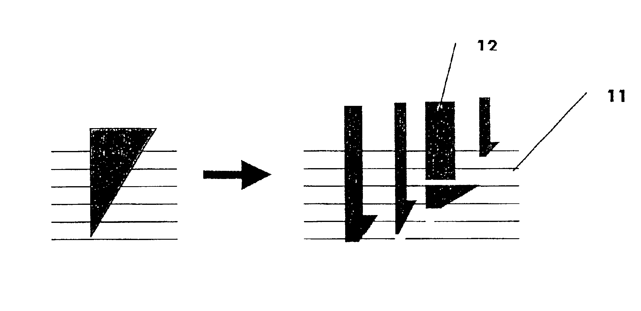
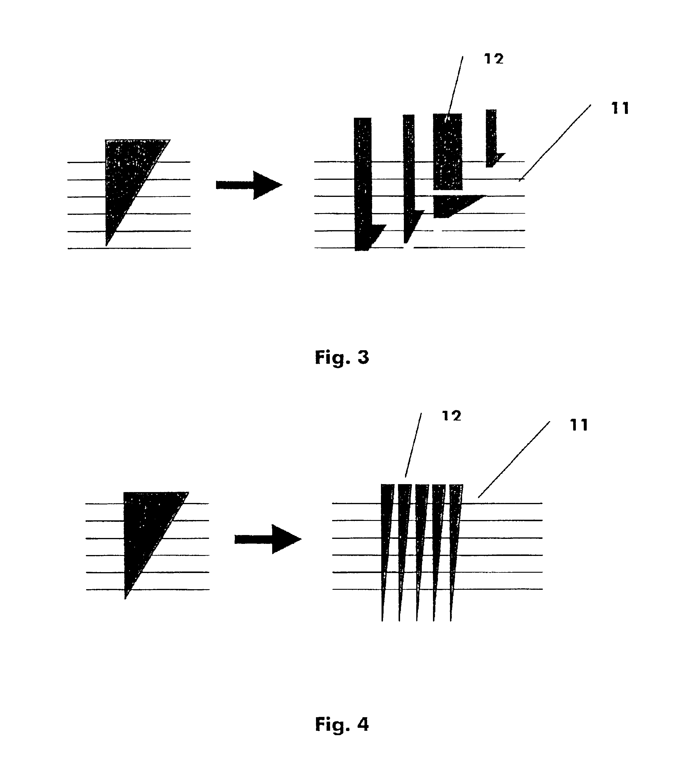
[0014]The invention proposes a design with a plurality of grooves in the second section of core region where the grooves of a first embodiment differs from each other by their widths. The widths are designed in a pseudo-randomized way, so that no relation between the widths of adjacent wedges occurs. This allows an effective reduction of cross talk effect. In a further embodiment of the invention a plurality of grooves are formed as second section of the c

Problems solved by technology

Unfortunately however, in practice, the operational performance of such devices is significantly affected by variations in the temperature of the environment surrounding the device.
Unfortunately, such a design is expensive and impractical in applications where electrical power is

Method used


Image

  • Optical device for reducing temperature related shift
  • Optical device for reducing temperature related shift
  • Optical device for reducing temperature related shift

Examples


Example

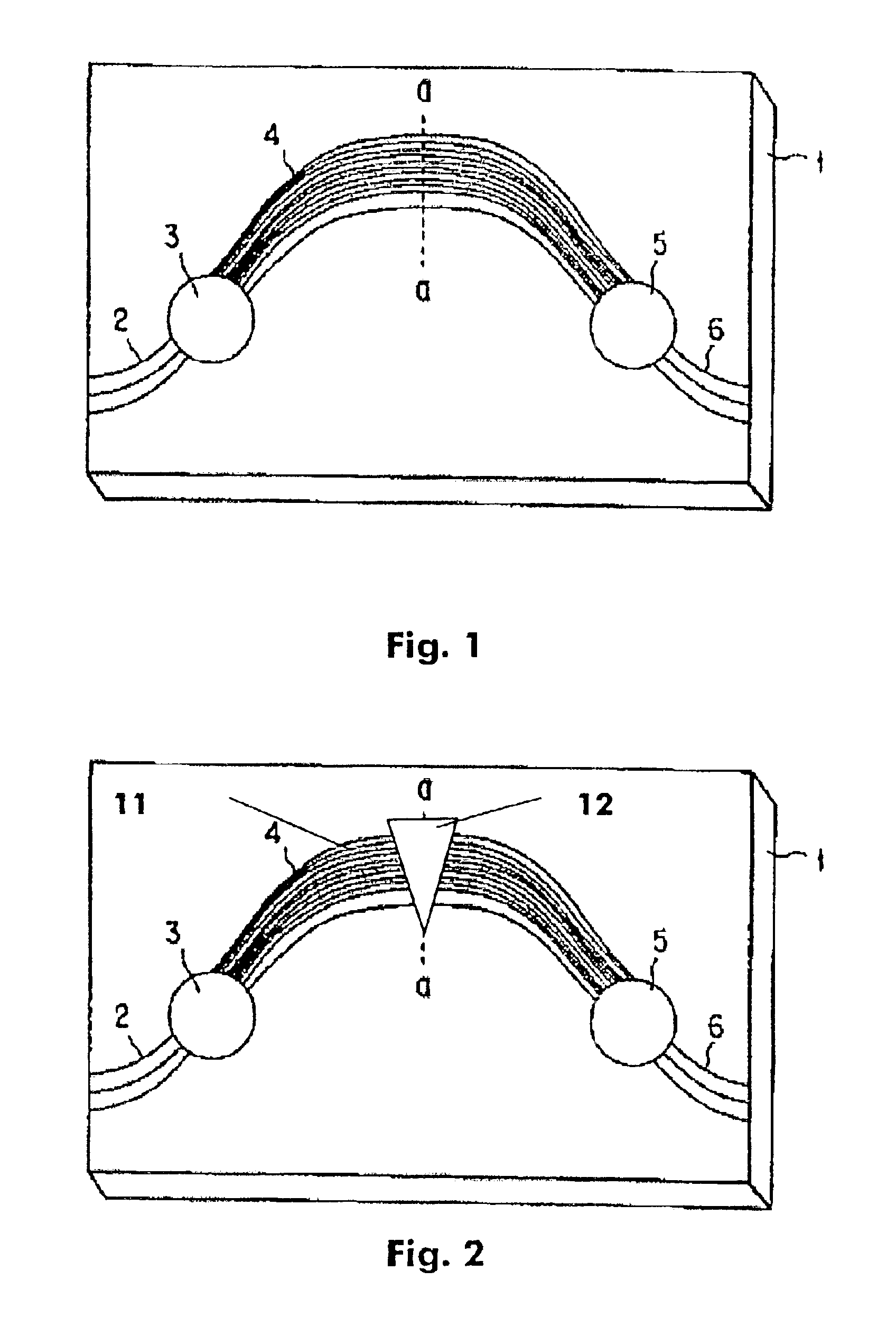
[0021]FIG. 1 shows a circuit diagram of a conventional arrayed waveguide grating multiplexer. The input waveguides 2 are connected to a first slab waveguide 3 and via an FIG. 2 shows an arrayed waveguide with two sections: a first arrayed waveguide 4 and a second slab waveguide 5 to the output waveguides 6.

[0022]FIG. 2 shows a athermal arrayed waveguide as described in prior art. The arrayed waveguide 4 comprises two sections with a first section made by silica and a second section made of an elastomeric material with a negative thermal coefficient. In order that optical phases in two adjacent waveguides are varied with respect to temperature change it is necessary that the difference of optical path lengths of the two adjacent waveguides are not varied with respect to temperature. When the temperature coefficient of the refractive index of the first section of the waveguide and the temperature coefficient of the second section of the waveguide have different values a broad groove i...


PUM


Abstract

The invention is an optical device having a plurality of optical waveguides and comprising at least one waveguide, which is defined by a core region having first and second sections that are series connected and are capable of transmitting light energy, the core region being surrounded by a cladding that essentially confines the light energy within the core region, the first section of the core region comprising a first length of material whose refractive index increases as temperature increases; the at least one waveguide is temperature-compensating in that and the second section of the core region comprises a second length of material whose refractive index has a sufficient enough difference of the rate of the variation of the index with the temperature, wherein the second section has a plurality of grooves, filled with the material whose refractive index has a sufficient enough difference of the rate of the variation of the index with the temperature, that are designed in a way the effective width of the second section changes between adjacent wave guides.

Description

BACKGROUND OF THE INVENTION[0001]The invention is based on a priority application EP 02 360 158.6 which is hereby incorporated by reference.[0002]Generally speaking, optical wavelength multiplexing and demultiplexing have been accomplished in the past by using an interconnection apparatus having a plurality of closely spaced input waveguides communicating with the input of a star coupler. The output of the star coupler communicates with an optical grating comprising a series of optical waveguides, each of the waveguides differing in length with respect to its nearest neighbor by a predetermined amount. The grating is connected to the input of a second star coupler, the outputs of which form the outputs of the switching, multiplexing, and demultiplexing apparatus.[0003]The geometry of such an interconnection apparatus may be such that a plurality of separate and distinct wavelengths each launched into a separate and distinct input port of the apparatus will all combine and appear on ...

Claims


Application Information

Patent Timeline
IPC IPC(8): G02B6/34
CPCG02B6/12011G02B6/12028G02B6/1203
Inventor LAZARO VILLA, JOSE ANTONIOMUNZNER, ROLAND
Owner OCLARO NORTH AMERICA
Learn More