Fiber optic cable having a low-shrink cable jacket and methods of manufacturing the same

a fiber optic cable and jacket technology, applied in the field of fiber optic cables, can solve the problems of increasing the bending radius of the fiber optic cable, the general unsuitability of small bending radius applications of fiber optic cables with anti-buckling characteristics, and the general inability of fiber optic cables without anti-bucking members to achieve optical performance degradation

Inactive Publication Date: 2005-08-02
CORNING OPTICAL COMM LLC
View PDF30 Cites 24 Cited by
  • Summary
  • Abstract
  • Description
  • Claims
  • Application Information

AI Technical Summary

Problems solved by technology

However, strength members having anti-buckling characteristics generally increase the stiffness of the fiber optic cable, thereby increasing the bending radius of the fiber optic cable.
Thus, fiber optic cables having strength members with anti-buckling characteristics are generally unsuitable for small bend radius applications, for example, splice trays and / or as an interconnect cable assembly.
However, fiber optic cables without anti-bucking members are generally susceptible to optical performance degradation due to shrinkage of the cable jacket during manufacture and / or due to ambient environmental changes in the field such as temperature and / or humidity.
However, the aramid fibers do not provide anti-buckling.
Consequently, the interconnect cable assembly is susceptible to optical performance degradation due to the shrinkage of the cable jacket because as the cable jacket shrinks the aramid fibers do not inhibit the optical fibers from becoming undulated and / or buckled.
This shrinkage of the cable jacket can result in an undulated cable core causing undesirable compressive axial stress and / or strains being applied to the cable core and / or optical fiber, which can cause undesirable optical attenuation.
Additionally, there are other sources of cable jacket shrinkage that may cause undesired optical degradation.
Such variations can result in, for example, cable jacket expansion and contraction.
For example, shrinkage of the cable jacket can cause undulation and / or buckling of the optical fiber(s), thereby resulting in undesired optical degradation in the interconnect cable assembly.
In general, insertion loss is an undesired result because it results in a weaker optical signal.
Fiber-to-fiber separation also implies an insertion loss due to Fresnel reflections at one of the two glass end interfaces.
This may generally inhibit the cable jacket from shrinking during the manufacturing process when the cable jacket is cooling after being extruded.
However, this results in a relatively stiff cable generally unsuitable for use in small bend radius applications and / or as an interconnect cable assembly.
However, this method requires mixing the different materials, which may result in a non-homogeneous mixture.
Additionally, mixing the materials of the cable jacket adds another level of complexity to the manufacturing process and can result in increased manufacturing costs.

Method used


Image

  • Fiber optic cable having a low-shrink cable jacket and methods of manufacturing the same
  • Fiber optic cable having a low-shrink cable jacket and methods of manufacturing the same
  • Fiber optic cable having a low-shrink cable jacket and methods of manufacturing the same

Examples


Embodiment Construction

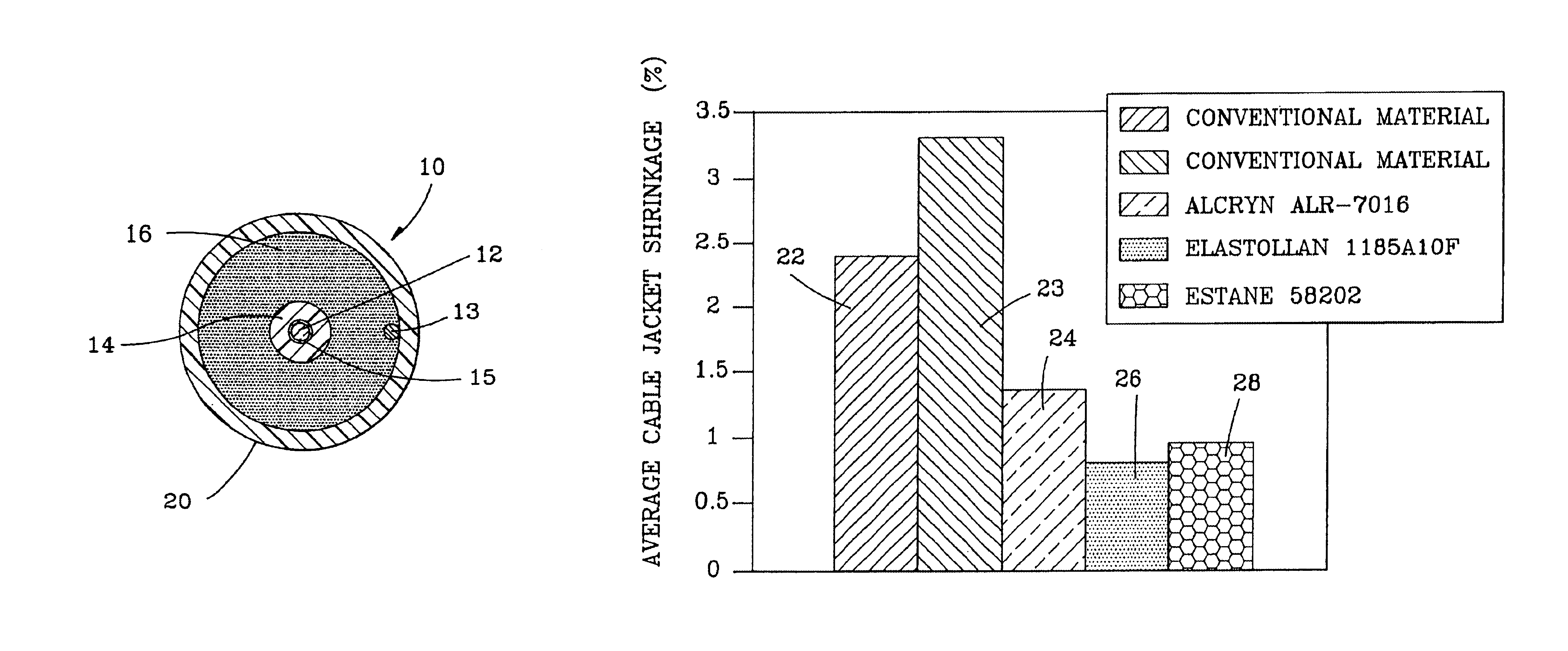
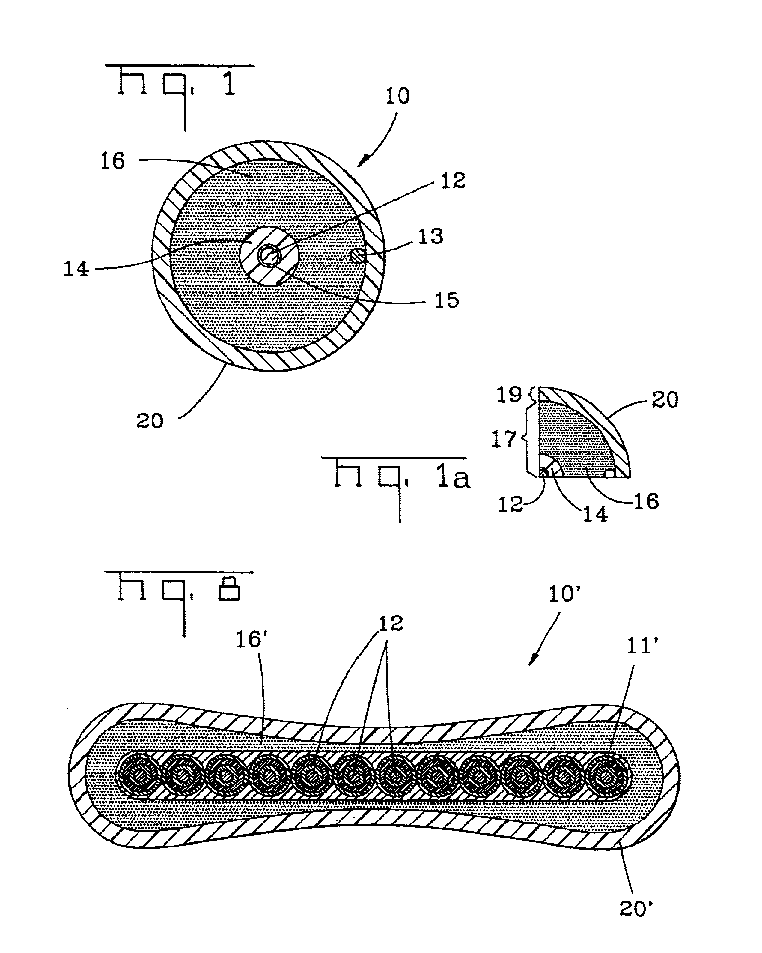
[0031]Referring to FIG. 1, the present invention will be described with reference to an exemplary fiber optic cable 10. Fiber optic cable 10 generally includes a cable core 17 and a cable sheath 19 (FIG. 1a). Cable core 17 generally includes at least one optical fiber 12 having a tight buffer layer 14 therearound and an interfacial layer 15; however, cable core 17 may include other suitable cable components or fewer cable components. Sheath 19 generally includes a cable jacket 20; however, sheath 19 may include other suitable cable components. Interfacial layer 15 is generally disposed between optical fiber 12 and tight buffer layer 14 to promote stripability of tight buffer layer 14. A separation layer 16 generally surrounds tight buffer layer 14 and inhibits cable jacket 20 from adhering thereto, thereby preserving optical performance. Cable jacket 20 according to the present invention includes a low-shrink characteristic, thereby preserving optical performance, for example, in re...


PUM


Abstract

A fiber optic cable and methods for manufacturing the same the fiber optic cable including a fiber optic cable core, the fiber optic cable core includes at least one optical fiber and a separation layer. The separation layer generally surrounds the at least one optical fiber, and a cable jacket generally surrounds the separation layer. The cable jacket has an average shrinkage of about 2.0% or less during a cable jacket shrinkage test conducted at a temperature of 110° C. for 2 hours with the cable core removed. The low-shrink characteristic of the cable jacket preserves optical performance during, for example, temperature variations.

Description

RELATED APPLICATIONS[0001]The present application is a Divisional of U.S. Ser. No. 10 / 038,073 filed on Jan. 4, 2002 now U.S. Pat. No. 6,801,695.FIELD OF THE INVENTION[0002]The present invention relates to fiber optic cables and, more particularly, to fiber optic cables having a cable jacket with a relatively low-shrink characteristic.BACKGROUND OF THE INVENTION[0003]Fiber optic cables include optical fibers that transmit signals, for example, voice, video, and / or data information. Optical fibers require cabling to protect the relatively fragile silica-based optical fibers and to preserve the optical performance thereof. For example, because optical fibers are not ductile they must be protected from external forces such as tensile forces. Additionally, optical fibers require protection from macro-bending and / or micro-bending to inhibit undesired optical degradation.[0004]In order to meet these requirements, fiber optic cables designed for indoor, outdoor, or indoor / outdoor applicatio...

Claims


Application Information

Patent Timeline
Patent Type & Authority Patents(United States)
IPC IPC(8): G02B6/44
CPCG02B6/443G02B6/4486G02B6/4403
Inventor LANIER, JENNIFER K.HALL, DONALD K.PATEL, NAREN I.
Owner CORNING OPTICAL COMM LLC
Why Eureka
Try Eureka