Method of feeding and installing self-attaching nuts

a self-attaching and nut technology, which is applied in the direction of de-stacking articles, instruments, manufacturing tools, etc., can solve the problems of linkage breakage and improper control of the travel of the feed pawl

Inactive Publication Date: 2005-08-09
WHITESELL FORMED COMPONENTS
View PDF23 Cites 42 Cited by
  • Summary
  • Abstract
  • Description
  • Claims
  • Application Information

AI Technical Summary

Benefits of technology

[0007]The present invention relates to an installation apparatus for installing self-attaching fasteners, particularly including pierce and clinch nuts, a feed mechanism for an installation head for feeding self-attaching fasteners interconnected by a frangible connector, and a method of installing a self-attaching fastener in a panel, wherein the feed mechanism includes a spring-biased feed pawl which feeds the first self-attaching fastener in the feed passage adjacent the plunger passage upon opening of the die press, thereby avoiding problems associated with the installation heads presently on the market. As set forth above, the installation apparatus of this invention includes a base member, which is conventionally attached to the upper shoe of a die press, having a plunger fixed relative to the base member and extending from the base member, a nose member spaced from the base member by a biasing element, such as a spring or pneumatic cylinder, wherein the nose member includes a feed passage and a plunger passage which receives the free end of the plunger, and a feed mechanism which feeds self-attaching fasteners through the feed passage into the plunger passage for installation in a panel located opposite the plunger passage.
[0010]In the disclosed embodiment of the feed mechanism of this invention, the feed pawl includes a finger adapted to be received in the nut bore of the first nut in the feed passage adjacent the plunger passage. Where only one nut remains in the feed passage, the end of the feed pawl engages the side of the last nut. However, the feed mechanism of this invention may also be utilized to feed a fastener strip having notches or projections on the exposed sides of the fasteners in the fastener strip as disclosed in a co-pending application assigned to the assignee of this application, wherein two feed pawls are pivotally supported on the slide bracket, thereby eliminating contact with the feed bore and also permitting feeding of fastener elements which do not have a bore or where it is not practical to feed the bore of the fastener. Further, where the feed system of this invention includes two feed pawls which engage notches or projections on the sides of the fasteners, it is possible to use a spring having a greater force which would otherwise damage the nut bore assuring feeding of the fasteners and permitting engagement of a fastener adjacent the plunger passage, but spaced from the plunger passage one or two fasteners thus reducing the likelihood of feed error.
[0012]Another problem relates to removal of a nut strip from the installation head such as disclosed in the above-referenced U.S. Pat. No. 3,845,860. As will be understood by those skilled in this art, the pierce nuts may be fed to the feed passage from a spool of nuts and the spool of nuts must be changed periodically by the die press operator. Thus, it would be convenient to be able to remove a small portion of a strip of nuts from the head prior to complete exhaustion of the spool. This is presently a difficult task primarily because of the design of the restrictor, which is a metal stamping. The release of the nut strip also requires a special tool. In the fastener installation head of this invention, the restrictor comprises a metal part, preferably a cast metal part, pivotally supported on the nose member, having a finger which extends into the first nut bore of the first nut adjacent the plunger passage. The finger is biased by a spring into the nut bore. The second leg of the feed pawl also includes a projecting portion which may be easily gripped by the operator. The nut strip may thus be easily removed from the fastener installation head simply by depressing the nut restrictor and the second leg portion of the feed pawl, releasing the nut strip and permitting removal of the nut strip from the fastener installation head.

Problems solved by technology

However, the fastener installation head disclosed in these patents was not successful because the feed pawl was connected to the base member by a linkage, wherein the feed pawl was positively actuated by the linkage upon closing of the die press resulting in breakage of the linkage due to tolerance variations, such that the travel of the feed pawl was not properly controlled.
However, the feed mechanism of this invention may also be utilized to feed a fastener strip having notches or projections on the exposed sides of the fasteners in the fastener strip as disclosed in a co-pending application assigned to the assignee of this application, wherein two feed pawls are pivotally supported on the slide bracket, thereby eliminating contact with the feed bore and also permitting feeding of fastener elements which do not have a bore or where it is not practical to feed the bore of the fastener.

Method used


Image

  • Method of feeding and installing self-attaching nuts
  • Method of feeding and installing self-attaching nuts
  • Method of feeding and installing self-attaching nuts

Examples


Embodiment Construction

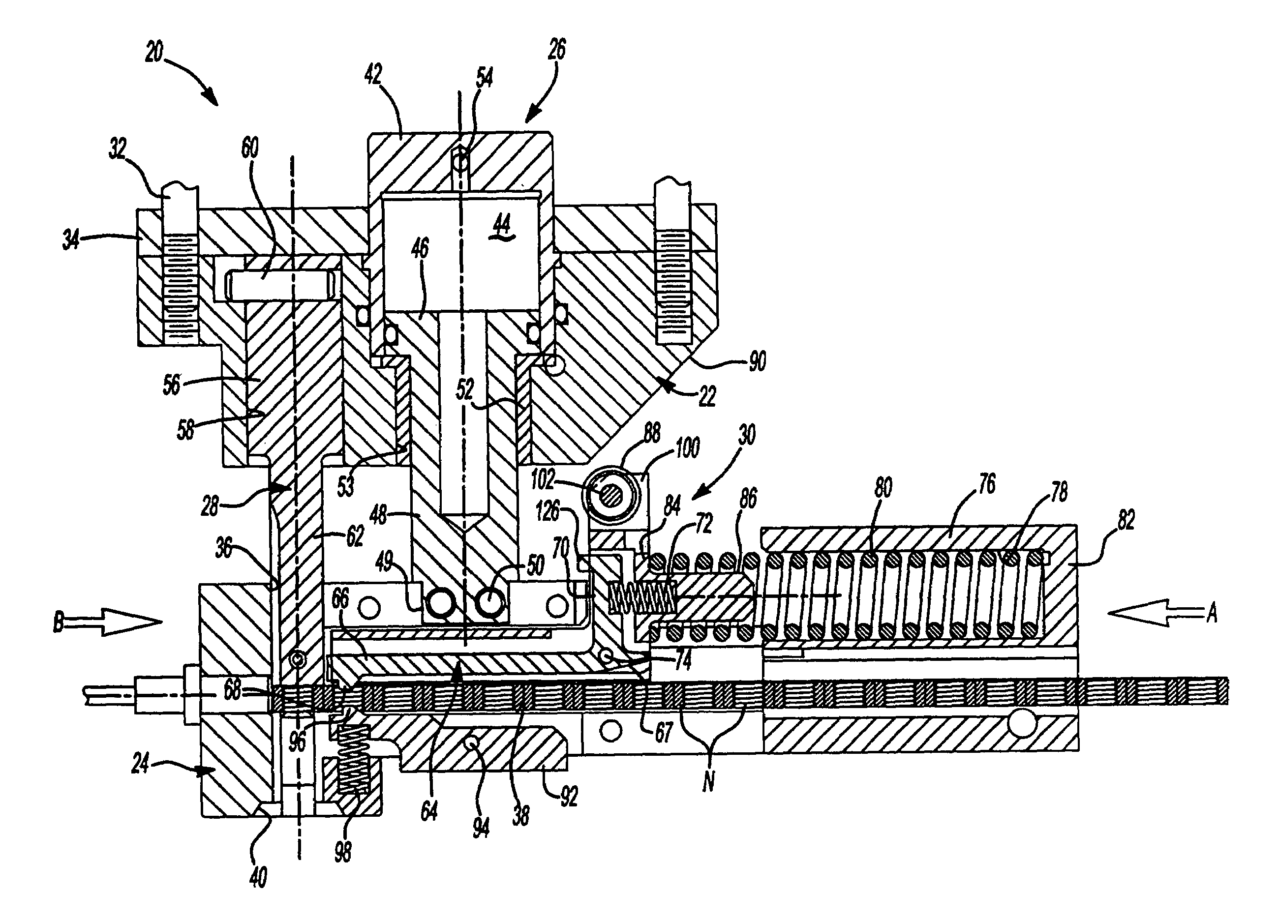
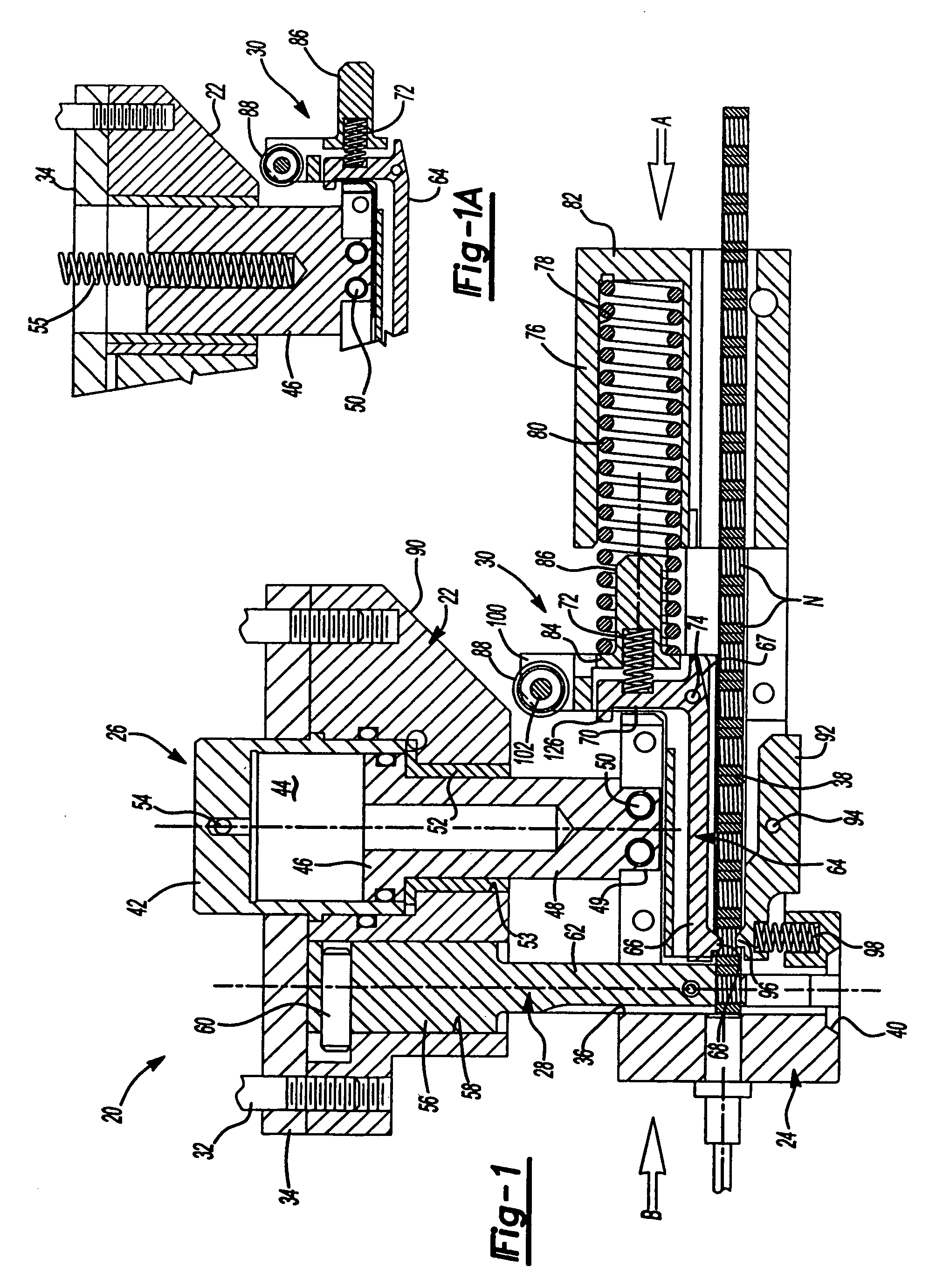
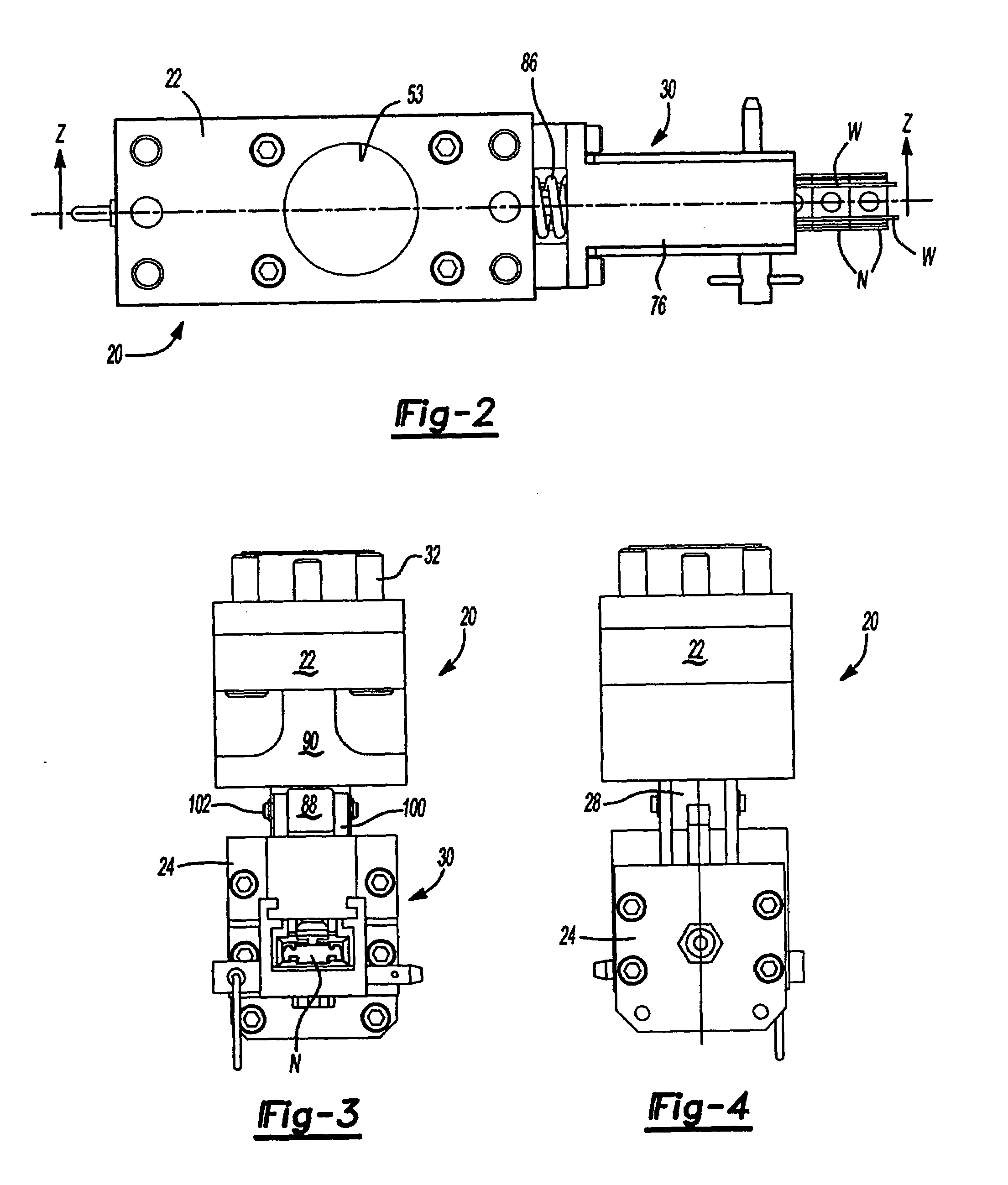
[0025]The embodiment of the fastener installation head 20 of this invention illustrated in FIG. 1 includes a base member 22, a nose member 24, a shank or guidepost assembly 26, a plunger 28 and a nut feed assembly 30. As set forth above, the base member 22 is generally attached to the upper die shoe or platen of a die press (not shown) by mounting bolts 32. In a typical application, a mounting or back-up plate 34 is provided between the base member 22 and the upper die platen (not shown). Shims (not shown) may also be provided between the mounting plate 34 and the upper die platen.

[0026]The nose member 24 includes a plunger passage 36 and a transverse nut feed passage 38 which receives the fasteners, such as nuts “N,” from the feed mechanism 30 as described below. The plunger passage 36 may also include an explosion relief 40 which avoids jamming of the plunger passage if the die press is operated to install a second nut over a nut already installed in the panel as will be understoo...


PUM

PropertyMeasurementUnit
resilientaaaaaaaaaa
sizeaaaaaaaaaa
forceaaaaaaaaaa

Abstract

A self-attaching fastener installation head and feed mechanism including a spring-biased L-shaped feed pawl which feeds a first nut in the feed passage adjacent the plunger passage on the upstroke of the die press. The feed pawl is pivotally supported on a slide bracket which includes a roller in the longitudinal axis of the feed passage which is biased against a central cam surface on the base and the base is interconnected to the nose member by removable pins. A spring biased nut restrictor is pivotally supported on the nose member, simplifying removal of a nut strip from the head and the installation head is more rugged in design and has fewer parts, reducing costs.

Description

RELATED APPLICATIONS[0001]This application is a division of application Ser. No. 10 / 138,446 filed May 3, 2002 now U.S. Pat. No. 6,631,827, which application claimed priority to provisional application Ser. No. 60 / 360,933, filed Mar. 1, 2002.BACKGROUND OF THE INVENTION[0002]The present invention relates to improvements in pierce and clinch nut installation heads of the type disclosed in U.S. Pat. No. 3,089,360 of Multifastener Corporation, the predecessor in interest of the assignee of this application. As disclosed in U.S. Pat. No. 3,089,360, the disclosure which is incorporated herein by reference, pierce and clinch nut installation heads, are typically attached to the upper die shoe or platen of a die press and the installation head simultaneously feeds the pierce or clinch nuts, either in strip or bulk form, to a plunger and installs a pierce or clinch nut through the plunger passage into a metal panel and a die button located in the opposite die shoe or platen permanently instal...

Claims


Application Information

Patent Timeline
Patent Type & Authority Patents(United States)
IPC IPC(8): B23P19/06B23P19/00
CPCB23P19/006B23P19/062Y10T29/5124Y10T29/49908Y10T29/49947Y10T29/53522Y10T29/53709Y10T29/5343Y10T29/49835
Inventor GOODSMITH, DALE H.LADOUCEUR, HAROLD A.VRANA, JOHN J.SICKELS, DAVID W.
Owner WHITESELL FORMED COMPONENTS
Why Eureka
Try Eureka